1. 製品概要
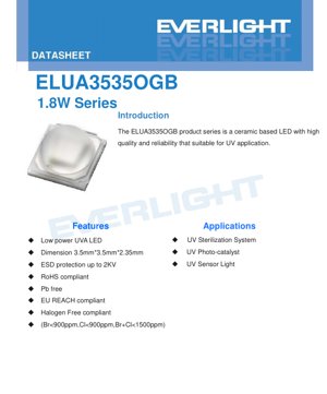
ELUA3535OGB製品シリーズは、紫外線(UVA)用途に特化して設計された、高信頼性のセラミックベースLEDソリューションです。その中核構造はAl2O3(酸化アルミニウム)セラミック基板を採用しており、従来のプラスチックパッケージと比較して優れた熱管理を実現し、過酷な条件下でも長寿命と安定した性能を発揮します。
中核的利点: The primary benefits of this series include its robust セラミックパッケージ for excellent heat dissipation, integrated ESD protection up to 2KV (Human Body Model), and compliance with major environmental and safety standards including RoHS, Pb-free, EU REACH, and halogen-free requirements (Br<900ppm, Cl<900ppm, Br+Cl<1500ppm). The 120-degree viewing angle offers a broad radiation pattern suitable for area illumination tasks.
Target Market & Applications: このLEDは、信頼性と光出力が重要な産業用および商業用UVアプリケーション向けに設計されています。主な応用分野には、空気および水の浄化のためのUV殺菌システム、表面処理および脱臭のためのUV光触媒システム、ならびにUVセンサーおよび硬化プロセスの光源としての使用が含まれます。
2. 技術パラメータ詳細解説
2.1 絶対最大定格
これらの定格は、デバイスに永久的な損傷が生じる可能性がある限界値を定義します。この条件下での動作は保証されません。
- Max. DC Forward Current (IF): 385nm、395nm、405nmタイプは1000mAまで対応。365nmタイプは、異なる半導体材料特性と熱感受性を反映し、最大電流は700mAにダウンレートされています。
- 最大ESD耐圧 (VB): 2000V (HBM)。良好な取り扱い耐性を提供します。
- 熱抵抗 (Rth): 4 °C/W。この低い値はセラミックパッケージによるもので、LED接合部から放熱パッドへの効率的な熱伝達を示しています。
- 最大接合部温度 (TJ): 125 °C。
- Operating & Storage Temperature: 動作時は-10〜+100°C、保管時は-40〜+100°C。
2.2 Photometric & Electrical Characteristics
この表は、標準試験電流500mAおよび放熱パッド温度25°Cにおける、異なる波長ビンの主要性能パラメータを示しています。
- ピーク波長: 4つのビンで利用可能:360-370nm (U36)、380-390nm (U38)、390-400nm (U39)、400-410nm (U40)。
- 放射束: 最小放射束は1000mW(U2ビン)で規定され、典型的な値は約1250mW、全ての波長グループにおける最大値は1500mWに達します。
- 順方向電圧(VF): 500mA時で3.2Vから4.0Vの範囲にあり、特定の電圧ビン(例:3.2-3.4V、3.4-3.6V)に分類されます。
3. ビニングシステムの説明
製品は一貫性を確保し、アプリケーションのニーズに基づいた精密な選択を可能にするために、ビンに分類されます。
3.1 放射束ビニング
放射束はIF=500mA、許容差±10%で測定される。ビン区分は以下の通り:
- U2: 1000mWから1200mW
- U3: 1200mWから1400mW
- U4: 1400mWから1500mW
3.2 ピーク波長ビニング
ピーク波長は±1nmの許容差で測定される。グループ(U36、U38、U39、U40)は、セクション2.2に記載されている波長範囲に対応する。
3.3 順方向電圧ビニング
順方向電圧はIF=500mA、許容差±2%で測定されます。ビン(3234、3436、3638、3840)は最小および最大VF 範囲(例:3234 = 3.2V から 3.4V)。
4. 性能曲線分析
4.1 Spectrum & Relative Radiant Flux vs. Current
スペクトルグラフは、365nm、385nm、395nm、405nmの各波長における典型的な発光曲線を示しています。これらの曲線は狭帯域であり、UV LEDの特徴です。相対放射束対順方向電流グラフは、定格電流まではほぼ線形の関係を示しており、同じ電流レベルでは、一般的に405nm LEDが最も高い相対出力を示し、次いで395nm、385nm、365nmの順となります。
4.2 Peak Wavelength & 順方向電圧 vs. Current
The Peak Wavelength vs. Forward Current plot shows minimal shift (<5nm) across the operating current range for all wavelengths, indicating good spectral stability. The 順方向電圧 vs. Forward Current curve shows the typical diode exponential characteristic, with VF 電流の増加に伴い上昇します。365nm LEDは通常、より長波長のバリアントよりもわずかに高いVF を示します。
4.3 温度依存性
相対放射束対周囲温度グラフは、温度上昇に伴い出力が低下することを示しており、これはLEDに共通の特性です。デレーティング曲線は設計上極めて重要です:それは、接合温度(TJ) は125°Cを超えない。例えば、周囲温度85°Cでは、最大電流は室温定格値から大幅に低下する。
4.4 放射パターン
典型的な放射パターンはランバート型で、中心に120度の全視野角(2θ1/2). このパターンは、焦点を絞ったビームよりも広域カバレッジを必要とするアプリケーションに適しています。
5. Mechanical & Packaging Information
5.1 Mechanical Dimensions
パッケージ外形寸法は3.5mm (L) x 3.5mm (W) x 2.35mm (H)です。図面には、放熱パッド(カソード)とアノードパッドの位置が規定されています。放熱パッドは中央に配置され、放熱を容易にするために大きく設計されています。特に断りのない限り、全ての寸法公差は±0.1mmです。
5.2 極性識別
LEDパッケージの上面にはアノードが表示されています。底面の放熱パッドはカソードと電気的に接続されています。基板実装時には正しい極性を遵守する必要があります。
6. Soldering & Assembly Guidelines
6.1 リフローはんだ付けプロセス
ELUA3535OGBは、標準的なSMT(Surface Mount Technology)リフロープロセスに適しています。主な指示事項は以下の通りです:
- 接着剤の硬化は、標準的なプロセスに従って行う必要があります。
- 熱ストレスを避けるため、リフローはんだ付けは2回を超えて行わないでください。
- 加熱および冷却中のLEDへの機械的ストレスは最小限に抑える必要があります。
はんだ付け後、基板を曲げないでください。セラミックパッケージやはんだ接合部の割れを防止するためです。
6.2 保管条件
LEDは、端子の酸化を防ぐため、元の防湿バッグに入れた状態で、温度-40°C〜+100°C、低湿度の環境で保管してください。
7. Model Nomenclature & Ordering Information
型番は詳細な構造に従います: ELUA3535OGB-PXXXXYY3240500-VD1M
- EL: メーカーコード。
- UA: UVA製品ファミリー。
- 3535: パッケージサイズ (3.5x3.5mm)。
- O: パッケージ材料 (Al2O3 セラミック).
- G: コーティング(Ag - 銀)。
- B: 視野角(120°)。
- PXXXX: ピーク波長コード(例:360-370nmの場合は6070)。
- YY: 最小放射束ビン(例:1000mWの場合はU2)。
- 3240: 順方向電圧範囲 (3.2-4.0V)。
- 500: 順方向電流定格 (500mA)。
- V: チップタイプ (垂直型)。
- D: チップサイズ (45mil)。
- 1: チップ数 (1)。
- M: プロセスタイプ(成形)。
8. アプリケーションの提案
8.1 代表的なアプリケーション回路
これらのLEDを安定動作させるには定電流ドライバが必要です。基本的な回路は、DC電源、定電流ドライバICまたは回路、そして直列接続されたLEDで構成されます。ドライバは、動作周囲温度に基づくデレーティングカーブを考慮しつつ、最大500mA(365nmの場合は700mA)を供給できるものを選択すべきです。内蔵のESD保護機能がある場合でも、電気的にノイズの多い環境では、サージ電圧抑制を検討することが望ましいです。
8.2 ヒートシンク設計
効果的な熱管理は極めて重要です。4 °C/Wという低い熱抵抗は、熱が放熱パッドから適切に導かれなければ効果を発揮しません。放熱パッドを大きな銅面または外部ヒートシンクに接続するサーミアルビアを備えた適切に設計されたPCBは、特に高電流時や周囲温度が高い環境で動作する場合に必須です。最大接合部温度(125°C)を超えてはなりません。
8.3 光学設計に関する考慮事項
殺菌および光触媒用途においては、対象表面への照度(単位面積あたりのUVパワー)が重要です。120度のビーム角は広範囲な照射を実現します。特定のポイントでより高い照度が必要な場合は、二次光学素子(反射器やレンズ)が必要になることがあります。光学素子および筐体の材料選定では、UV透過性とUV劣化への耐性(例:石英、UVグレードガラス、PTFEなどの特定のUV安定プラスチックの使用)を考慮する必要があります。
9. Technical Comparison & Differentiation
ELUA3535OGBシリーズは、その セラミックパッケージプラスチックSMD UV LEDと比較して、セラミックは以下の利点を提供します:
- 優れた熱性能: より低い熱抵抗は、同じ駆動電流で動作接合温度を低下させ、これは直接的に長寿命(L70/B50)および高い維持出力に繋がります。
- 信頼性の向上: セラミックは不活性であり、湿気や環境汚染物質に対する密閉に近い障壁を提供し、過酷な条件下での性能を向上させます。
- より高い電力密度: 堅牢なパッケージにより、1.8Wの高出力レベルでの信頼性の高い動作が可能であり、この物理的サイズのLEDとしては高水準に位置します。
10. よくあるご質問 (FAQ)
10.1 波長以外で、365nm版と405nm版の違いは何ですか?
主な違いは半導体材料の組成であり、それにより電気的・光学的特性が異なります。365nm LEDは最大定格電流が低く(700mA対1000mA)、通常、順方向電圧がわずかに高く、同じ電流での放射束出力も低くなります。また、温度に対する感度も高くなります。選択は、特定の用途で必要な波長(例:特定の光触媒には365nm、一部の硬化プロセスには405nm)によって決まります。
10.2 デレーティング曲線はどのように解釈すればよいですか?
デレーティング曲線は、特定の周囲温度(LEDのサーマルパッドで測定)における最大安全動作順方向電流を定義します。使用方法は、x軸に予想される最大周囲温度を見つけ、曲線まで線を引き、次にy軸まで左に線を引いて最大許容電流を求めます。その温度でこの電流を超えないようにドライバーを設計する必要があります。例えば、周囲温度が60°Cの場合、最大電流は約400mAです。
10.3 このLEDを定電圧源で駆動できますか?
強く推奨されません。LEDは定電流駆動デバイスです。その順方向電圧は負の温度係数を持ち、個体間でばらつきがあります(電圧ビンに示されている通り)。定電圧駆動は熱暴走を引き起こす可能性があります:LEDが加熱するにつれて、VF 電圧降下により電流が増加し、さらなる発熱を引き起こし、Vがさらに低下するF そして電流が増加し、故障に至る。常に定電流ドライバーを使用すること。
11. Design & Usage Case Study
11.1 事例:接着剤用UV硬化ステーション
シナリオ: 小型電子部品上のUV感光性接着剤を硬化させるための卓上ステーションの設計。
選定: 405nmバリアント(ELUA3535OGB-P0010U23240500-VD1M)が選択された理由は、多くの工業用UV硬化接着剤が400nm付近で効率的に硬化するように配合されているためです。
設計: 均一な硬化エリアを形成するため、アルミコアPCB(MCPCB)上に16個のLEDアレイを配置する計画です。各LEDは定電流ドライバにより500mA定格以下となる450mAで駆動され、寿命を向上させます。MCPCBはファン付きの大型アルミヒートシンクに取り付けられます。デレーティングカーブを参照すると、内部アンビエント温度が45°Cと推定される条件下では、450mAは安全動作領域内に十分収まります。120度のビーム角により、隣接するLED間の良好な重なりが確保され、均一性が得られます。
結果: このステーションは、迅速な硬化のための一貫性の高い高照度UV光を提供し、セラミックパッケージにより長期間の安定した出力を保証します。
12. 原理の紹介
UVA LEDは、半導体材料におけるエレクトロルミネッセンスの原理に基づいて動作する。p-n接合に順方向電圧を印加すると、電子と正孔が活性領域に注入される。それらの再結合により、エネルギーが光子として放出される。発光の波長(色)は、活性領域で使用される半導体材料のバンドギャップエネルギーによって決定される。UVA光(315-400nm)の場合、InGaN/AlGaNなどの材料が特殊な基板上に用いられることが一般的である。セラミックパッケージは主に、機械的に頑丈で熱伝導性の高いプラットフォームとして、チップ内の非発光再結合プロセスに伴う副産物である熱を放散する役割を果たす。
13. 開発動向
UV LED市場、特にUVAおよびUVB分野は、環境規制(水俣条約)による水銀灯の段階的廃止によって牽引されている。主な動向としては以下が挙げられる:
効率向上(WPE - Wall-Plug Efficiency): 現在の研究は、内部量子効率と光取り出し効率の向上に焦点を当て、電気ワット当たりの光出力を増大させ、システムのエネルギーコストと熱負荷を低減することです。
Higher Power & Power Density: 先進的なセラミックスや複合基板などの優れた熱材料により、同じまたはより小さな占有面積からより高い放射束を提供するシングルダイLEDおよびマルチチップパッケージの開発が進められています。
Improved Reliability & Lifetime: チップ設計、パッケージ材料(ここで使用されているセラミックなど)、蛍光体技術(波長変換UV製品向け)の向上は、産業および医療用途における重要な要素である動作寿命の延長を目指しています。
コスト削減: 製造量の増加とプロセスの成熟に伴い、放射ワット当たりのコストは低下すると予想され、より多くの用途への採用が加速します。
LED仕様用語集
LED技術用語の完全解説
光電性能
| 用語 | ユニット/表現 | 簡単な説明 | 重要性 |
|---|---|---|---|
| 発光効率 | lm/W (ルーメン毎ワット) | ワット当たりの光束、数値が高いほど省エネ性能が優れていることを示します。 | エネルギー効率等級と電気料金を直接決定します。 |
| Luminous Flux | lm(ルーメン) | 光源から放射される光の総量。一般的に「明るさ」と呼ばれる。 | 光が十分に明るいかどうかを判定します。 |
| 視野角 | ° (度)、例:120° | 光強度が半減する角度、ビーム幅を決定する。 | 照射範囲と均一性に影響する。 |
| CCT (色温度) | K (ケルビン), 例: 2700K/6500K | 光の温かみ/冷たさ。値が低いと黄色みがかった温かみ、高いと白っぽい冷たさを帯びる。 | 照明の雰囲気と適切なシナリオを決定します。 |
| CRI / Ra | 無次元、0〜100 | 物体の色を正確に再現する能力、Ra≥80は良好。 | 色の忠実度に影響し、商業施設や博物館などの高要求場所で使用。 |
| SDCM | MacAdam楕円ステップ、例:「5ステップ」 | 色の一貫性メトリック、ステップが小さいほど色の一貫性が高いことを意味します。 | 同一バッチのLED間で均一な色を保証します。 |
| Dominant Wavelength | nm(ナノメートル)、例:620nm(赤) | カラーLEDの色に対応する波長。 | 赤、黄、緑の単色LEDの色調を決定します。 |
| Spectral Distribution | 波長対強度曲線 | 波長にわたる強度分布を示す。 | 演色性と品質に影響する。 |
電気的特性
| 用語 | シンボル | 簡単な説明 | 設計上の考慮事項 |
|---|---|---|---|
| 順方向電圧 | Vf | LEDを点灯させる最小電圧、「始動閾値」のようなもの。 | ドライバー電圧はVf以上でなければならず、直列LEDでは電圧が加算される。 |
| Forward Current | If | 通常のLED動作時の電流値。 | Usually constant current drive, current determines brightness & lifespan. |
| 最大パルス電流 | Ifp | 短時間許容ピーク電流、調光や点滅に使用。 | Pulse width & duty cycle must be strictly controlled to avoid damage. |
| 逆電圧 | Vr | LEDが耐えられる最大逆電圧。これを超えると破壊の可能性があります。 | 回路は逆接続や電圧スパイクを防止する必要があります。 |
| Thermal Resistance | Rth (°C/W) | チップからはんだへの熱伝達抵抗。低いほど良い。 | 熱抵抗が高い場合は、より強力な放熱が必要です。 |
| ESD耐性 | V (HBM)、例:1000V | 静電気放電耐性、数値が高いほど影響を受けにくい。 | 生産時には静電気対策が必要、特に感度の高いLEDに対して。 |
Thermal Management & Reliability
| 用語 | 主要指標 | 簡単な説明 | 影響 |
|---|---|---|---|
| 接合部温度 | Tj (°C) | LEDチップ内部の実際の動作温度。 | 10°C低下するごとに寿命が倍増する可能性あり;高すぎると光減衰、色ずれを引き起こす。 |
| Lumen Depreciation | L70 / L80 (時間) | 初期輝度の70%または80%まで低下するまでの時間。 | LEDの「寿命」を直接定義する。 |
| 光束維持率 | % (例: 70%) | 時間経過後の輝度保持率。 | 長期使用における輝度保持を示す。 |
| Color Shift | Δu′v′またはマクアダム楕円 | 使用時の色変化の程度。 | 照明シーンにおける色の一貫性に影響を与える。 |
| Thermal Aging | 材料劣化 | 長期高温による劣化。 | 輝度低下、色変化、または開放故障を引き起こす可能性があります。 |
Packaging & Materials
| 用語 | 一般的な種類 | 簡単な説明 | Features & Applications |
|---|---|---|---|
| パッケージタイプ | EMC, PPA, セラミック | ハウジング材料がチップを保護し、光学的/熱的インターフェースを提供します。 | EMC: 耐熱性に優れ、低コスト; セラミック: 放熱性がより良く、寿命が長い。 |
| Chip Structure | フロント、フリップチップ | チップ電極配置。 | フリップチップ:放熱性に優れ、高効率、大電力用途向け。 |
| 蛍光体コーティング | YAG, Silicate, Nitride | 青色チップをカバーし、一部を黄/赤に変換し、混合して白色を生成する。 | 異なる蛍光体は、効率、CCT、CRIに影響を与える。 |
| レンズ/光学系 | フラット、マイクロレンズ、TIR | 表面の光学構造による配光制御。 | 視野角と光配光曲線を決定する。 |
Quality Control & Binning
| 用語 | ビニングコンテンツ | 簡単な説明 | 目的 |
|---|---|---|---|
| 光束ビン | コード例:2G、2H | 明るさでグループ化され、各グループには最小/最大ルーメン値があります。 | 同一ロット内での均一な輝度を保証します。 |
| Voltage Bin | Code e.g., 6W, 6X | 順方向電圧範囲によるグループ化。 | ドライバーとのマッチングを容易にし、システム効率を向上させます。 |
| カラービン | 5-step MacAdam ellipse | 色座標でグループ化し、狭い範囲を確保。 | 色の一貫性を保証し、照明器具内での色むらを防止します。 |
| CCT Bin | 2700K、3000Kなど | 相関色温度(CCT)ごとにグループ化され、それぞれに対応する座標範囲があります。 | 異なるシーンのCCT要件を満たします。 |
Testing & Certification
| 用語 | 規格・試験 | 簡単な説明 | 重要性 |
|---|---|---|---|
| LM-80 | 光束維持試験 | 恒温条件下での長期点灯、輝度減衰を記録。 | LED寿命の推定に使用(TM-21と併用)。 |
| TM-21 | 寿命推定基準 | LM-80データに基づき、実際の使用条件下での寿命を推定します。 | 科学的な寿命予測を提供します。 |
| IESNA | 照明学会 | 光学、電気、熱に関する試験方法を網羅。 | 業界で認知された試験基準。 |
| RoHS / REACH | 環境認証 | 有害物質(鉛、水銀)を含まないことを保証します。 | 国際的な市場参入要件。 |
| ENERGY STAR / DLC | エネルギー効率認証 | 照明器具のエネルギー効率および性能認証。 | 政府調達、補助金プログラムに使用され、競争力を高めます。 |