Yaliyomo
- 1. Muhtasari wa Bidhaa
- 2. Detailed Technical Parameters
- 2.1 Absolute Maximum Ratings
- 2.2 Electro-Optical Characteristics
- 3. Performance Curve Analysis
- 3.1 Relationship Between Forward Current and Ambient Temperature
- 3.2 Spectral Distribution
- 3.3 Relationship Between Forward Current and Forward Voltage (I-V Curve)
- 3.4 Relationship Between Radiant Intensity and Forward Current
- 3.5 Relationship Between Relative Radiant Intensity and Angular Displacement
- 4. Mechanical and Packaging Information
- 4.1 Package Dimensions
- 4.2 Pad Design and Stencil Recommendations
- 4.3 Polarity Marking
- 5. Soldering and Assembly Guide
- 5.1 Moisture Sensitivity and Storage
- 5.2 Reflow Soldering Process
- 5.3 Uuzaji wa Mikono na Urekebishaji
- 5.4 Usindikaji wa Bodi ya Mzunguko
- 6. Ufungaji na Taarifa za Kuagiza
- 6.1 Vipimo vya Mkanda na Reel
- 6.2 Label Specifications
- 7. Application Recommendations
- 7.1 Typical Application Scenarios
- 7.2 Design Considerations
- 8. Technical Comparison and Differentiation
- 9. Frequently Asked Questions (Based on Technical Parameters)
- 9.1 Can I drive this LED directly from a 3.3V or 5V microcontroller pin?
- 9.2 What is the difference between the 20mA DC rating and the 100mA pulse rating?
- 9.3 How to understand the 25-degree "viewing angle"?
- 9.4 Why are moisture sensitivity and baking important?
- 10. Practical Design and Application Cases
- 11. Working Principle
- 12. Mienendo na Maendeleo ya Sekta
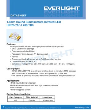
1. Muhtasari wa Bidhaa
HIR26-21C/L289/TR8 ni diode inayotoa mionzi ya infrared ya aina ya SMD yenye ukubwa mdogo sana. Imebuniwa hasa kwa matumizi yanayohitaji chanzo cha mwanga cha infrared kinachoshikamana na cha kuaminika, na inaendana na mchakato wa kisasa wa usanikishaji wa kiotomatiki. Kifaa hiki kinatumia kifurushi cha duara chenye kipenyo cha milimita 1.6, chenye kifurushi cha plastiki chenye uwazi na lenzi ya juu ya duara ili kuboresha utoaji wake wa mwanga.
Faida yake kuu ni uendanaji wa wigo wake na vigunduzi vya mwanga vya silicon (photodiode na phototransistor), na kukifanya kiwe na ufanisi mkubwa katika mifumo ya kugundua. Kifaa hiki kinatengenezwa kwa kutumia nyenzo ya chip ya GaAlAs (Gallium Aluminum Arsenide), ambayo ni nyenzo ya kawaida kwa vitoa mionzi ya infrared vya utendaji wa juu katika safu hii ya urefu wa wimbi.
Soko lengwa linajumuisha wabunifu na watengenezaji wa vifaa vya elektroniki vya matumizi ya kaya, vigunduzi vya viwanda, na vifaa vya kiotomatiki, ambavyo matumizi yake yana nafasi ndogo na yanahitaji usambazaji wa ishara ya infrared unaoaminika au kugundua.
2. Detailed Technical Parameters
2.1 Absolute Maximum Ratings
These ratings define the limits beyond which permanent damage to the device may occur. Operation outside these limits is not recommended.
- Continuous Forward Current (IF)): 65 mA. This is the maximum DC current that can be applied continuously at an ambient temperature (Ta) of 25°C.
- Peak Forward Current (IFP)): 1.0 A. This high current is only permitted under pulse conditions with a pulse width ≤100μs and a duty cycle ≤1%. This is typically used in remote control applications requiring brief, high-power pulses.
- Reverse Voltage (VR)): 5 V. Exceeding this reverse bias voltage may cause junction breakdown.
- Operating Temperature (Topr)): -40°C to +85°C. This device is suitable for industrial temperature ranges.
- Storage Temperature (Tstg)): -40°C to +100°C.
- Soldering Temperature (Tsol)): 260°C, duration not exceeding 5 seconds, compatible with lead-free reflow process.
- Power Dissipation (Pd)): 130 mW at a free-air temperature of 25°C or below. This rating considers electrical power conversion and the device's heat dissipation capability.
2.2 Electro-Optical Characteristics
These parameters are measured at Ta=25°C and define the device's performance under typical operating conditions.
- Radiant Intensity (Ie)): Optical power output per unit solid angle (steradian). At a forward current of 20mA, the typical value is 17 mW/sr (minimum 10 mW/sr). Under pulsed conditions (100mA, ≤100μs, duty cycle ≤1%), the typical radiant intensity increases significantly to 85 mW/sr, highlighting the advantage of pulsed operation for peak output.
- Peak Wavelength (λp)): 850 nm (typical value). This falls within the near-infrared spectrum, is very suitable for silicon-based detectors, and is less visible to the human eye than shorter wavelengths such as 940nm, while still maintaining good atmospheric transmittance.
- Spectral Bandwidth (Δλ)): 30 nm (typical value). This defines the range of emission wavelengths centered around the peak wavelength.
- Forward Voltage (VF)): At 20mA, the typical forward voltage is 1.40V (range 1.20V to 1.70V). At a 100mA pulsed current, VFincreases to a typical value of 1.60V (range 1.40V to 2.20V). This information is crucial for driver circuit design and power supply selection.
- Reverse Current (IR)): Maximum 10 μA at a reverse voltage of 5V, indicating good junction quality.
- Viewing Angle (2θ1/2)): 25 degrees (typical). This is the full angle at which the radiation intensity drops to half of its peak (axial) value. The 25° angle provides a relatively focused beam, suitable for directional sensing or signal transmission.
3. Performance Curve Analysis
The datasheet provides several key graphs for understanding the device's behavior under different conditions.
3.1 Relationship Between Forward Current and Ambient Temperature
This curve shows the maximum allowable continuous forward current decreasing as the ambient temperature rises above 25°C. To prevent overheating, the current must be linearly reduced as the temperature approaches the maximum operating limit of 85°C. Designers must use this graph to ensure reliable operation within the thermal environment of their application.
3.2 Spectral Distribution
This graph plots relative radiant intensity versus wavelength, visually confirming the 850nm peak and the spectral bandwidth of approximately 30nm. It shows the device emits relatively pure infrared light centered at the specified wavelength.
3.3 Relationship Between Forward Current and Forward Voltage (I-V Curve)
Mkunjo huu wa msingi wa sifa unaonyesha uhusiano wa kielelezo kati ya mkondo na voltage ya diode. Ni muhimu sana kwa kubainisha sehemu ya kufanya kazi na kubuni saketi za kudhibiti mkondo. Mkunjo huu hubadilika na mabadiliko ya joto.
3.4 Relationship Between Radiant Intensity and Forward Current
Grafu hii inaelezea pato la mwanga kama kitendakazi cha mkondo wa kuendesha. Kwa kawaida huonyesha uhusiano wa chini ya mstari, na kwenye mikondo ya juu sana, ufanisi (nguvu ya mionzi kwa kila mA) unaweza kupungua kwa sababu ya athari za joto na athari nyingine. Grafu hii husaidia kuboresha mkondo wa kuendesha kwa kiwango kinachohitajika cha pato la mwanga.
3.5 Relationship Between Relative Radiant Intensity and Angular Displacement
Grafu hii ya kuratibu polar inaonyesha kwa urahisi mtazamo wa pembe na muundo wa mionzi wa LED. Inaonyesha nguvu inavyopungua wakati pembe ya uchunguzi inapotoka kwenye mhimli wa kati (0°), ikishuka hadi 50% kwenye takriban ±12.5° (ikithibitisha mtazamo kamili wa pembe wa 25°). Hii ni muhimu sana kwa kubuni mifumo ya macho, usawazishaji, na kuelewa eneo linalofunikwa na mwanga unaotolewa.
4. Mechanical and Packaging Information
4.1 Package Dimensions
Kifaa hiki ni cha ufungaji wa SMD wenye ncha mbili, na kipenyo kikuu cha 1.6mm. Mchoro wa kina wa mitambo katika spec sheet hutoa vipimo vyote muhimu, ikiwa ni pamoja na urefu wa jumla, umbali wa pini, na jiometri ya lenzi. Isipokuwa imebainishwa vinginevyo, vipimo vyote viko katika milimita, na uvumilivu wa kawaida ni ±0.1mm.
4.2 Pad Design and Stencil Recommendations
Ili kuhakikisha unyweo unaotegemewa na kuepuka matatizo kama vile mipira ya solder, muundo ulipendekezwa wa pad na stencil umetolewa. Mapendekezo muhimu ni pamoja na:
- Paste ya solder: Sn/Ag3.0/Cu0.5 (a common lead-free alloy).
- Stencil Thickness: 0.10mm.
- The stencil aperture design shows a pattern intended to control the solder paste volume for small pads.
Important Note: The recommended pad dimensions are for reference only. The final PCB pad pattern should be modified according to specific manufacturing processes, thermal requirements, and individual design needs.
4.3 Polarity Marking
The cathode is typically indicated by a visual marker on the package, such as a notch, a flat edge, or a green mark on the base. The datasheet drawing clearly identifies the cathode side, which is crucial for correct PCB orientation.
5. Soldering and Assembly Guide
5.1 Moisture Sensitivity and Storage
This device is moisture sensitive. Precautions must be taken to prevent "popcorning" (package cracking due to rapid vapor expansion during reflow soldering).
- Do not open the moisture barrier bag until ready for use.
- After opening, store at ≤30°C and ≤60% relative humidity (RH).
- Tumia ndani ya masaa 168 (siku 7) baada ya kufungua mfuko.
- Ikiwa muda wa uhifadhi umepita au kiwango cha unyevu kwenye driers kinaonyesha kuingia kwa unyevu, kausha vipengele kwa saa 24 kwenye 60 ±5°C kabla ya matumizi.
5.2 Reflow Soldering Process
Kifaa hiki kinaendana na michakato ya kuyeyusha tena ya infrared na vapor phase. Mkunjo wa joto wa kuyeyusha tena usio na risasi unapendekezwa kwenye datasheet. Vigezo muhimu vinajumuisha joto la awali, kudumisha joto, kiwango cha juu cha joto cha kuyeyusha tena (kisizozidi 260°C, kwa muda wa ≤ sekunde 5), na kiwango cha kupoa. Kuyeyusha tena haipaswi kuzidi mara mbili ili kupunguza mkazo wa joto kwenye vipengele.
5.3 Uuzaji wa Mikono na Urekebishaji
Ikiwa uchongaji wa mkono lazima ufanyike, uangalifu mkubwa unahitajika:
- 使用烙铁头温度<350°C的烙铁。
- 每个端子接触时间限制在≤3秒。Tumia chuma cha kulehemu chenye uwezo wa 25W au chini.
- Punguza muda wa ≥ sekunde 2 kati ya kulehemu kila terminali ili kuzuia mkusanyiko wa joto.
- Urekebishaji baada ya kulehemu kwa mara ya kwanza haupendekezwi. Ikiwa haliwezi kuepukika, wakati wa kuondoa tumia chuma cha kulehemu chenye vichwa viwili ili kupasha joto terminali zote mbili kwa wakati mmoja, ili kuzuia mkazo wa mitambo kwenye sehemu za kulehemu na LED yenyewe. Baada ya urekebishaji wowote, hakikisha kuthibitisha utendaji kazi wa kifaa.
5.4 Usindikaji wa Bodi ya Mzunguko
Epuka kutumia mkazo wa mitambo kwenye LED wakati wa mchakato wa kupasha joto (kulehemu), na usipinde bodi ya mzunguko baada ya kulehemu, kwani hii inaweza kusababisha kifaa au sehemu zake za kulehemu kupasuka.
6. Ufungaji na Taarifa za Kuagiza
6.1 Vipimo vya Mkanda na Reel
The device is supplied in embossed carrier tape on industry-standard 7-inch diameter reels. A detailed drawing of the carrier tape dimensions (pocket size, pitch, etc.) is provided. Each reel contains 1500 pieces.
6.2 Label Specifications
The reel label contains standard information for traceability and manufacturing:
- CPN (Customer Part Number)
- P/N (Manufacturer Part Number: HIR26-21C/L289/TR8)
- QTY (Quantity)
- CAT (Category/Bin)
- HUE (Peak Wavelength)
- REF (Reference)
- LOT No. (Lot Number)
- MSL-X (Moisture Sensitivity Level)
- Made In (Country of Origin)
7. Application Recommendations
7.1 Typical Application Scenarios
- PCB Mounted Infrared Sensor: Proximity sensing, object detection, line following in robotics.
- Infrared Remote Control Unit: Suitable for applications requiring higher output power than standard remote control LEDs, potentially achieving longer distances or better performance in bright environments.
- Gas Counter/Meter: Commonly used for optical sensing mechanisms within utility meters.
- General-Purpose Infrared System: Any embedded system requiring a compact, reliable infrared light source for data transmission, encoding, or sensing.
7.2 Design Considerations
- Current Limiting is MandatoryKama ilivyoelezwa wazi katika "Vitu vya Kuzingatia," ni lazima kutumia upinzani wa kudhibiti nje (au kiendesha cha mkondo wa mara kwa mara) kwa mfululizo na LED. Voltage ya mbele ina safu, na ikiwa haijadhibitiwa ipasavyo, ongezeko dogo la voltage ya usambazaji linaweza kusababisha ongezeko kubwa na la uharibifu la mkondo.
- Usimamizi wa jotoZingatia matumizi ya nguvu (Pd=VF*IF) pamoja na kupunguzwa kwa mkondo wa juu zaidi kulingana na joto. Hakikisha kuna sahani ya shaba ya PCB ya kutosha au njia nyingine za kupoza joto, hasa katika matumizi ya joto la mazingira ya juu au mfululizo wa mapigo ya uwiano wa juu.
- Ubunifu wa machoPembe ya kuona ya 25° hutoa mwelekeo. Kwa usambazaji mpana zaidi, vifaa vya macho vya sekondari (vipenyezaji) vinaweza kuhitajika. Kwa umbali mrefu zaidi, lenzi zinaweza kutumika kusawazisha mwale.
- Saketi ya kiendeshaFor pulse operation at 1A, a transistor or MOSFET switch is required. Ensure the driver can handle the peak current and the required fast rise/fall times.
8. Technical Comparison and Differentiation
Compared to standard 5mm or 3mm through-hole infrared LEDs, the HIR26-21C/L289/TR8 offers significant advantages:
- SizeThe 1.6mm SMD package enables miniaturization of end products and is compatible with high-speed SMT assembly.
- PerformanceThe typical 17 mW/sr radiant intensity at 20mA is competitive, while 85 mW/sr under pulse conditions is a key feature for high-output requirements.
- Reliability: Muundo wa SMD na uendeshaji na mchakato wa kawaida wa reflow, ikilinganishwa na vipengele vya mashimo vinavyochomwa kwa mikono, huleta viunganisho vya kuunganishwa vilivyo thabiti na thabiti zaidi.
- Kufuata:该器件无铅,符合RoHS、REACH标准,且无卤素(Br <900ppm,Cl <900ppm,Br+Cl <1500ppm),满足全球市场的严格环保法规。
9. Frequently Asked Questions (Based on Technical Parameters)
9.1 Can I drive this LED directly from a 3.3V or 5V microcontroller pin?
Hapana.Voltage ya kawaida ya mbele ni 1.4V-1.6V tu. Ikiwa haitumii upinzani wa kuzuia mkondo na kuunganishwa moja kwa moja kwenye chanzo cha 3.3V au 5V, karibu hakika LED itaharibika kutokana na mkondo mkubwa. Hakikisha unatumia upinzani wa mfululizo uliohesabiwa kulingana na sheria ya Ohm: R = (VPower supply- VF) / IF.
9.2 What is the difference between the 20mA DC rating and the 100mA pulse rating?
The 20mA rating is suitable forcontinuousoperation. The 100mA rating is suitable for very shortpulse(≤100μs) na uwiano wa chini ya mzunguko (≤1%). Hii inaruhusu LED kuendeshwa kwa nguvu zaidi kwa muda mfupi, kutoa mwanga mkali zaidi (85 mW/sr ikilinganishwa na 17 mW/sr) bila kuchoka, kwani nguvu ya wastani bado ni ndogo. Hii inafaa kabisa kwa kifaa cha kudhibiti kwa mbali.
9.3 How to understand the 25-degree "viewing angle"?
Hii ndio pembe ambayo ukubwa wa mwanga ni nusu ya thamani yake ya juu zaidi (mhimlili).全Inaweza kuchukuliwa kama upana wa "boriti" kuu au petali ya mwanga. Kuna mwanga unaotolewa nje ya pembe hii, lakini kwa nguvu dhaifu. Pembe ya 25° inalenga kwa wastani.
9.4 Why are moisture sensitivity and baking important?
Vifurushi vya plastiki vya SMD hunyonya unyevunyevu kutoka kwa hewa. Wakati wa mchakato wa kiwango cha juu cha reflow soldering, unyevunyevu huu hubadilika haraka kuwa mvuke, na kusababisha shinikizo la ndani ambalo linaweza kusababisha ufa wa kifurushi au kutenganisha kwenye chip ("popcorn" effect). Kufuata miongozo ya uhifadhi na upasuaji kunaweza kuzuia aina hii ya kushindwa.
10. Practical Design and Application Cases
Mazingira: Kutengeneza alama ya infrared ya umbali mrefu
The designer requires a compact, battery-powered beacon that can be detected by a sensor 20 meters away in an indoor environment with some ambient infrared noise.
- Drive Method SelectionTo maximize detection range, the designer chooses pulsed operation to utilize a pulsed radiant intensity of up to 85 mW/sr.
- Circuit DesignA microcontroller GPIO pin controls an N-channel MOSFET. The LED is connected in series with a current-limiting resistor between the power supply (e.g., 3.3V) and the MOSFET drain. The resistor value is calculated for 100mA: R = (3.3V - 1.6V) / 0.1A = 17Ω (using a standard 18Ω value). The microcontroller generates pulses with a width of 100μs and a duty cycle of 1% (e.g., 100μs on, 9900μs off).
- PCB LayoutStart with the recommended pad layout. Add additional thermal pads and copper pour around the pads to aid heat dissipation during high-current pulses.
- AssemblyPlace components on the PCB. Store the LED reel properly. Perform a single reflow soldering on the assembled board using the recommended lead-free profile.
- Optics (Optional)To further extend the distance, a simple plastic collimating lens can be placed above the LED to narrow the beam, concentrating the output power into a smaller area at the target distance.
This case demonstrates how key datasheet parameters—pulse radiant intensity, forward voltage, current rating, and package size—directly guide practical design.
11. Working Principle
An Infrared Light Emitting Diode (IR LED) operates based on the principle of electroluminescence in a semiconductor p-n junction. When a forward voltage is applied, electrons from the n-type material and holes from the p-type material are injected into the junction region. When these charge carriers recombine, they release energy. In a GaAlAs diode like this one, the bandgap of the semiconductor material is engineered so that the released energy corresponds to photons in the infrared spectrum, specifically at a wavelength of approximately 850 nm. The transparent epoxy package acts as a lens, shaping the emitted light into the specified radiation pattern (25° viewing angle).
12. Mienendo na Maendeleo ya Sekta
The ultra-miniature infrared LED market continues to evolve. Key trends associated with devices like the HIR26-21C/L289/TR8 include:
- Increased Integration: The trend is to integrate infrared emitters with driver ICs and even photodetectors into a single package to simplify sensor modules.
- Higher Efficiency: Ongoing materials science research aims to improve the wall-plug efficiency (optical power output / electrical power input) of IR LEDs, enabling lower power consumption or higher output for the same package size.
- New Wavelengths: Ingawa 850nm na 940nm zinatawala, kwa matumizi maalum (kama kugundua gesi au kuimarisha usalama wa macho), hamu ya urefu mwingine wa mawimbi ya infrared inaongezeka.
- Ufungashaji wa Hali ya Juu: Kukuza Ufungashaji wa Kiwango cha Chip (CSP) na ufungashaji wa kiwango cha wafersi, ili kupunguza zaidi ukubwa na gharama, wakati huo huo kuboresha utendaji wa joto.
- Upanuzi wa Matumizi:
- Utambuzi wa Kibiolojia na Usalama: Utambuzi wa uso, Uchanganuzi wa iris.
- MagariIn-cabin occupant sensing, driver monitoring systems.
- Consumer ElectronicsProximity sensing and gesture recognition for mobile phones/tablets.
- Industrial Internet of ThingsMachine vision, condition monitoring.
Devices like the HIR26-21C/L289/TR8, with their compact form factor, reliable performance, and compliance with environmental standards, are well-suited to serve these expanding markets where compact, efficient infrared light sources are a fundamental requirement.
Detailed Explanation of LED Specification Terminology
Complete Explanation of LED Technical Terminology
I. Viashiria Muhimu vya Utendaji wa Umeme na Mwanga
| Istilahi | Kipimo/Uwakilishi | Maelezo ya Kawaida | Kwa Nini Ni Muhimu |
|---|---|---|---|
| Ufanisi wa Mwanga (Luminous Efficacy) | lm/W (lumen kwa watt) | Mwangaza unaotolewa kwa kila kitengo cha umeme, ufanisi wa juu zaidi unamaanisha matumizi bora ya nishati. | Huamua moja kwa moja kiwango cha ufanisi wa taa na gharama ya umeme. |
| Mfumuko wa Mwanga (Luminous Flux) | lm (lumen) | Jumla ya mwanga unaotolewa na chanzo cha mwanga, unaojulikana kwa jina la "mwangaza". | Huamua kama taa inatosha kuwa na mwangaza. |
| Pembe ya kuona mwanga (Viewing Angle) | ° (digrii), kama 120° | Pembe ambayo nguvu ya mwanga hupungua hadi nusu, huamua upana wa boriti ya mwanga. | Huathiri eneo la mwanga na usawa wake. |
| Joto la rangi (CCT) | K (Kelvin), k.m. 2700K/6500K | Joto la rangi ya mwanga, thamani ya chini inaelekea manjano/joto, thamani ya juu inaelekea nyeupe/baridi. | Huamua mazingira ya taa na matumizi yanayofaa. |
| Kielelezo cha uonyeshaji rangi (CRI / Ra) | Hakuna kipimo, 0–100 | Uwezo wa chanzo cha mwanga kuonyesha rangi halisi ya kitu, Ra≥80 ni bora. | Inaathiri ukweli wa rangi, hutumika katika maeneo yenye mahitaji makubwa kama maduka makubwa, majumba ya sanaa. |
| Tofauti ya Uwezo wa Rangi (SDCM) | Hatua za Duaradufu za MacAdam, kama "5-step" | Kipimo cha kiasi cha usawa wa rangi, idadi ndogo ya hatua inaonyesha usawa mkubwa wa rangi. | Kuhakikisha hakuna tofauti ya rangi kati ya taa za kundi moja. |
| Wavelength Kuu (Dominant Wavelength) | nm (nanomita), k.m. 620nm (nyekundu) | Thamani ya wavelength inayolingana na rangi ya LED ya rangi. | Huamua hue ya LED ya rangi moja kama nyekundu, manjano, kijani, n.k. |
| Usambazaji wa Wigo (Spectral Distribution) | Mkunjo wa Wavelength vs. Nguvu | Inaonyesha usambazaji wa nguvu ya mwanga unaotolewa na LED katika kila wavelength. | Inaathiri ubora wa kuonyesha rangi na ubora wa rangi. |
Mbili, Vigezo vya Umeme
| Istilahi | Ishara | Maelezo ya Kawaida | Mazingatio ya Ubunifu |
|---|---|---|---|
| Forward Voltage (Forward Voltage) | Vf | Voltage ya chini inayohitajika kuwasha LED, kama "kizingiti cha kuanzisha". | Voltage ya chanzo cha usukumaji lazima iwe ≥ Vf, voltage inajumlishwa wakati LED nyingi zimeunganishwa mfululizo. |
| Forward Current | If | Thamani ya mkondo inayofanya LED ionyeshe mwanga kwa kawaida. | Kwa kawaida hutumia usukumaji wa mkondo wa kudumu, mkondo huamua mwangaza na maisha ya huduma. |
| Mkondo wa juu zaidi wa msukumo (Pulse Current) | Ifp | Mkondo wa kilele unaoweza kustahimili kwa muda mfupi, hutumika kudhibiti mwangaza au kwa umeme. | Upana wa msukumo na uwiano wa kazi lazima udhibitiwe kwa uangalifu, vinginevyo kunaweza kuharibika kwa joto. |
| Voltage ya nyuma (Reverse Voltage) | Vr | Maksimum voltage ya nyuma ambayo LED inaweza kustahimili, ikiwa inazidi hii inaweza kuvunjika. | Mzunguko unahitaji kuzuia uunganishaji kinyume au mshtuko wa voltage. |
| Upinzani wa joto (Thermal Resistance) | Rth (°C/W) | Upinzani wa joto kutoka chip hadi sehemu ya kuuza, thamani ya chini inaonyesha usambazaji bora wa joto. | Upinzani wa joto wa juu unahitaji muundo wa usambazaji wa joto wenye nguvu zaidi, vinginevyo joto la kiungo litaongezeka. |
| Electrostatic Discharge Immunity (ESD Immunity) | V (HBM), e.g., 1000V | Electrostatic strike resistance capability; a higher value indicates greater resistance to electrostatic damage. | Anti-static measures must be implemented during production, especially for high-sensitivity LEDs. |
III. Thermal Management and Reliability
| Istilahi | Key Indicators | Maelezo ya Kawaida | Athari |
|---|---|---|---|
| Joto la Kiungo (Junction Temperature) | Tj (°C) | Joto halisi la uendeshaji ndani ya chip ya LED. | Kwa kila kupungua kwa 10°C, maisha yanaweza kuongezeka mara mbili; joto la juu sana husababisha kupungua kwa mwanga, na mabadiliko ya rangi. |
| Kupungua kwa Mwanga (Lumen Depreciation) | L70 / L80 (saa) | Muda unaohitajika kwa mwangaza kupungua hadi 70% au 80% ya thamani ya awali. | Inafafanua moja kwa moja "maisha ya huduma" ya LED. |
| Kiwango cha Kudumisha Lumeni (Lumen Maintenance) | % (k.m. 70%) | Asilimia ya mwangaza uliobaki baada ya kipindi fulani cha matumizi. | Inaonyesha uwezo wa kudumisha mwangaza baada ya matumizi ya muda mrefu. |
| Color Shift | Δu′v′ or MacAdam Ellipse | Kiwango cha mabadiliko ya rangi wakati wa matumizi. | Huathiri ufanani wa rangi katika eneo la taa. |
| Thermal Aging | Kupungua kwa Utendaji wa Nyenzo | Uharibifu wa nyenzo za kufunga kutokana na joto la juu kwa muda mrefu. | Inaweza kusababisha kupungua kwa mwangaza, mabadiliko ya rangi, au kushindwa kwa mzunguko wazi. |
Nne. Ufungaji na Nyenzo
| Istilahi | Aina za Kawaida | Maelezo ya Kawaida | Sifa na Matumizi |
|---|---|---|---|
| Package Type | EMC, PPA, Ceramic | The housing material that protects the chip and provides optical and thermal interfaces. | EMC offers good heat resistance and low cost; ceramic provides superior heat dissipation and long lifespan. |
| Chip Structure | Front-side, Flip Chip | Chip electrode arrangement method. | Flip chip offers better heat dissipation and higher luminous efficacy, suitable for high-power applications. |
| Phosphor coating | YAG, silicate, nitride | Coated on the blue LED chip, partially converting to yellow/red light, mixing to form white light. | Different phosphors affect luminous efficacy, color temperature, and color rendering. |
| Lens/Usanifu wa Optics | Uso wa gorofa, microlens, kutafakari kwa jumla | Muundo wa optics kwenye uso wa ufungaji, udhibiti wa usambazaji wa mwanga. | Huamua pembe ya mwanga na mkunjo wa usambazaji wa mwanga. |
Tano, Udhibiti wa Ubora na Uainishaji
| Istilahi | Yaliyomo ya Uainishaji | Maelezo ya Kawaida | Purpose |
|---|---|---|---|
| Luminous Flux Binning | Codes such as 2G, 2H | Grouped by brightness level, each group has a minimum/maximum lumen value. | Ensure consistent brightness for products within the same batch. |
| Voltage Binning | Codes such as 6W, 6X | Grouped by forward voltage range. | Facilitates driver matching and improves system efficiency. |
| Color Binning | 5-step MacAdam Ellipse | Grouped by color coordinates to ensure color falls within a minimal range. | Ensure color consistency to avoid uneven colors within the same luminaire. |
| Color temperature binning | 2700K, 3000K, etc. | Group by color temperature, each group has a corresponding coordinate range. | Meet the color temperature requirements of different scenarios. |
VI. Testing and Certification
| Istilahi | Standard/Test | Maelezo ya Kawaida | Significance |
|---|---|---|---|
| LM-80 | Lumen Maintenance Test | Long-term operation under constant temperature conditions, recording luminance attenuation data. | Used to estimate LED lifetime (combined with TM-21). |
| TM-21 | Kigezo cha kukadiria maisha | Kukadiria maisha chini ya hali halisi za matumizi kulingana na data ya LM-80. | Kutoa utabiri wa kisayansi wa maisha. |
| IESNA Standard | IESNA Standard | Covers optical, electrical, and thermal testing methods. | Industry-recognized testing basis. |
| RoHS / REACH | Environmental certification. | Ensures products are free from hazardous substances (e.g., lead, mercury). | Entry requirements for the international market. |
| ENERGY STAR / DLC | Uthibitisho wa ufanisi wa nishati. | Uthibitisho wa ufanisi wa nishati na utendaji kwa bidhaa za taa. | Hutumiwa kwa mikataba ya serikali, miradi ya ruzuku, na kuimarisha ushindani wa soko. |