Table of Contents
- 1. Product Overview
- 2. Key Features and Advantages
- 3. Maelezo ya Vipimo vya Kiufundi
- 3.1 Viwango vya Juu Kabisa
- 3.2 Electro-Optical Characteristics
- 4. Performance Curves and Chart Data
- 5. Mechanical Structure, Packaging and Assembly Information
- 5.1 Pin Configuration and Schematic
- 5.2 Package Dimensions and Mounting
- 5.3 Device Marking
- 5.4 Mwongozo wa Uchimbaji na Uendeshaji
- 6. Habari ya Ufungaji na Maagizo
- 6.1 Model Naming Rules
- 6.2 Packaging Specifications
- 7. Application Guide and Design Considerations
- 7.1 Target Application
- 7.2 Key Design Considerations
- 8. Technology Comparison and Selection Guide
- 9. Frequently Asked Questions (FAQ)
- 9.1 Je, SSR hii inaweza kubadili mzigo wa AC?
- 9.2 What are the differences between Connection Methods A, B, and C?
- 9.3 How to calculate power consumption and heat generation?
- 9.4 Is a Heat Sink Required?
- 10. Working Principle
- 11. Mazingira ya Sekta na Mwelekeo wa Maendeleo
1. Product Overview
This document details a series of general-purpose Solid State Relays (SSRs) configured in a 6-pin DIP (Dual In-line Package). These devices are single-pole, single-throw (Form A) relays, providing normally open (NO) contacts. They are designed to broadly replace traditional electromechanical relays (EMRs), offering superior reliability, longer service life, and silent operation due to their design without moving parts.
Their core technology involves an AlGaAs infrared LED on the input side, optically coupled to a high-voltage output detection circuit. This detection circuit, composed of a photovoltaic diode array and MOSFETs, is capable of controlling both AC and DC loads. The optical isolation provides a high isolation voltage (5000 Vrms) between the low-voltage control circuit and the high-voltage load circuit, enhancing system safety and noise immunity.
2. Key Features and Advantages
- Normally-open (Form A) configuration:Simple single-channel switch.
- Low operating current:The input LED requires extremely low drive current, making it compatible with low-power logic circuits and microcontrollers.
- Wide output voltage range:Models available with output withstand voltage from 60V to 600V (EL606A, EL625A, EL640A, EL660A), meeting the requirements of different application voltage levels.
- Low On-Resistance:MOSFET-based output provides low conduction loss, improving efficiency and reducing heat generation.
- Wide Operating Temperature Range:Reliable operation from -40°C to +85°C, suitable for industrial and harsh environments.
- High Isolation Voltage:Uwiano wa kutengwa kati ya pembejeo na pato wa Vrms 5000 unahakikisha usalama na kulinda vifaa vya elektroniki vyenye unyeti.
- Uthibitisho wa Sekta:Imethibitishwa kupitia viwango vya UL 1577, UL 508, VDE, SEMKO, NEMKO, DEMKO, FIMKO na CQC, ikihakikisha kufuata mahitaji ya kimataifa ya usalama na utendaji.
- Chaguo za Ufungaji:Inatoa tofauti za pini za kawaida za DIP zenye mashimo na zile za kufungia kwenye uso (SMD).
3. Maelezo ya Vipimo vya Kiufundi
3.1 Viwango vya Juu Kabisa
These are stress limits beyond which permanent damage to the device may occur. Operation should always be maintained within these limits.
- Input (LED side):Maximum forward current (IF) is 50 mA, with a peak forward current (IFP) of 1 A under pulse conditions. The reverse voltage (VR) is limited to 5 V.
- Output (switch side):The breakdown voltage (VL) defines the maximum blocking voltage the output can withstand, ranging from 60V (EL606A) to 600V (EL660A). The continuous load current (IL) varies by model and connection type (A, B, C), from 50 mA to 800 mA. The pulse load current (ILPeak) is also specified for short-term surges.
- Isolation:Can withstand 5000 Vrms voltage for 1 minute between input and output.
- Thermal Characteristics:Operating temperature range is -40°C to +85°C. Storage temperature up to 125°C. Maximum soldering temperature is 260°C for 10 seconds.
3.2 Electro-Optical Characteristics
Vigezo hivi vinafafanua utendaji wa SSR kwenye 25°C.
- Tabia za Ingizo:LED在10mA时的典型正向电压(VF)为1.18V。反向漏电流(IR)极低(<1 µA)。
- Output Characteristics - Off State:The leakage current (Ileak) of the SSR in the off state is specified to be a maximum of 1 µA, indicating its excellent blocking capability.
- Sifa za Pato - Hali ya Uendeshaji:Kigezo muhimu ni Upinzani wa Uendeshaji (Rd(ON)). Thamani hii hutofautiana kwa kiasi kikubwa kati ya aina tofauti na aina za muunganisho:
- Njia ya Muunganisho A:Highest rated current, highest Rd(ON) (e.g., EL606A: typical 0.75Ω, maximum 2.5Ω).
- Connection method B:Balanced ratings, medium Rd(ON).
- Connection method C:Lower rated current, lowest Rd(ON) (e.g., EL606A: typical 0.2Ω, maximum 0.5Ω).
- Output Capacitor (Cout):Mbalimbali kutoka 30 pF hadi 85 pF. Uwezo mdogo wa umeme unafaa kwa kubadili mzunguko wa juu ili kupunguza hasara.
- Tabia ya Usafirishaji:Inafafanua mkondo wa pembejeo unaohitajika kwa kuwasha pato kwa uhakika (IF(on), upeo wa 3 mA) na mkondo wa pembejeo unaohitajika kuzima pato (IF(off), chini ya 0.4 mA). Hii inahakikisha kizingiti wazi cha kubadili.
- Kasi ya Kubadili:Turn-on time (Ton) typically ranges from 0.35 ms to 1.3 ms. Turn-off time (Toff) is very fast, with a typical value of 0.1 ms. While these speeds are slower than some SSRs, they are sufficient for many industrial control applications.
- Isolation Parameters:隔离电阻(RI-O)极高(>5×10¹⁰ Ω),隔离电容(CI-O)较低(典型值1.5 pF)。
4. Performance Curves and Chart Data
The datasheet contains typical characteristic curves (though not detailed in the provided text). These curves typically illustrate:
- Forward Voltage vs. Forward Current (Vf-If):For the input LED, display its diode-like characteristics.
- On-Resistance vs. Load Current (Rd(ON)-IL):Show how Rd(ON) varies with the amount of switching current.
- On-state Resistance vs. Ambient Temperature (Rd(ON)-Ta):It is crucial for thermal design because Rd(ON) typically increases with temperature, leading to higher losses.
- Transfer Characteristic Graph:Piga grafu ya hali ya pato (WASHI/IMEZIMWA) dhidi ya mkondo wa pembejeo wa LED, kufafanua wazi viwango vya kuwasha/kuzima na ucheleweshaji.
Mikondo hii ni muhimu sana kwa wabunifu kuelewa tabia ya kifaa chini ya hali zisizo za kawaida au zinazobadilika, zaidi ya thamani ya kawaida ya 25°C.
5. Mechanical Structure, Packaging and Assembly Information
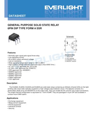
5.1 Pin Configuration and Schematic
The 6-pin DIP features a standard pinout:
- Pin 1: LED Anode (+)
- Pini 2: Kathodi ya LED (-)
- Pini 4, 6: Drain ya MOSFET (Terminal ya pato, kwa DC kawaida hubadilishana)
- Pini 5: Source ya MOSFET (Terminal ya pato ya pamoja)
- Pin 3: Internally not connected (NC), can be used for mechanical stability.
5.2 Package Dimensions and Mounting
Provides detailed mechanical drawings:
- Standard DIP type:For through-hole PCB mounting.
- Chaguo S1 (nyembamba ya kufungia kwenye uso):Inatumika kwa usanidi wa SMD.
- Mpango wa pedi unaopendekezwa:Kwa toleo la SMD, hakikisha kuwa muundo wa mshono unaundwa ipasavyo wakati wa kuchomea kwa kujirudia.
5.3 Device Marking
Sehemu ya juu ya kifaa imewekwa alama na msimbo: kiambishi awali "EL", nambari ya sehemu (mfano 660A), msimbo wa mwaka wa tarakimu 1 (Y), msimbo wa wiki wa tarakimu 2 (WW), na msimbo wa chaguo la VDE (V). Hii inarahisisha ufuatiliaji wa nyuma.
5.4 Mwongozo wa Uchimbaji na Uendeshaji
Kulingana na viwango vya juu kabisa:
- Uchomeaji wa reflow (SMD):The peak temperature must not exceed 260°C, and the time above 260°C should be limited to within 10 seconds to prevent damage.
- Wave soldering/Hand soldering (DIP):Apply standard procedures, but thermal stress should be minimized.
- ESD Prevention Measures:Although based on MOSFET, the output is protected by photovoltaic drive. Standard ESD handling procedures are recommended for sensitive components.
- Storage:Store under dry and anti-static conditions within a temperature range of -40°C to +125°C.
6. Habari ya Ufungaji na Maagizo
6.1 Model Naming Rules
Nambari ya sehemu inafuata muundo ufuatao:EL6XXA(Y)(Z)-V
- XX:Define the part number for output voltage/current (06, 25, 40, 60).
- Y:Pin form option. 'S1' indicates surface mount thin type. Blank indicates standard DIP.
- Z:SMD component reel packaging options (TA, TB, TU, TD). Blank indicates tube packaging.
- V:Indicates VDE safety certification option.
6.2 Packaging Specifications
- DIP ya kawaida:Tube packaging, 65 pieces per tube.
- Surface Mount (S1):Tape and reel packaging, 1000 pieces per reel. Detailed tape dimensions (pocket size A, B, hole Do, D1, pitch E, F) and reel specifications are provided for automatic placement machine setup.
7. Application Guide and Design Considerations
7.1 Target Application
SSR hizi zinafaa kwa matumizi mengi yanayohitaji kubadili kwa uaminifu na kwa kutengwa:
- Mawasiliano na Vifaa vya Kubadilishia:Signal Routing, Line Card Interfaces.
- Test and Measurement Equipment:Switching Sensor Inputs, Multiplexing Signals.
- Ufundishaji wa Otomatiki wa Kiwanda (FA) na Ufundishaji wa Otomatiki wa Ofisi (OA):Kudhibiti vali za sumakuumeme, injini ndogo, taa na vichocheji joto.
- Mfumo wa Kudhibiti Viwanda (ICS):PLC output module, the interface between the logic circuit and the power circuit.
- Security system:Switching power for alarms, door locks, or cameras.
7.2 Key Design Considerations
- Input Drive Circuit:Use a current-limiting resistor in series with the LED. Calculate the resistor value based on the supply voltage (e.g., 3.3V, 5V, 12V), the desired LED current (typically 5-10mA to ensure turn-on), and the LED's VF. Ensure the drive circuit can provide at least the maximum IF(on) (3mA) and can pull down below IF(off) (0.4mA) to guarantee turn-off.
- Output Load Considerations:
- Voltage Rating:Select a model where the maximum load voltage (including transient voltage) is below the device's VL rating (EL606A/625A/640A/660A). Derating (e.g., using a 400V component for a 240VAC line) is good practice.
- Current Rating:Select based on continuous RMS or DC load current. Consider the trade-offs of connection types (A/B/C). Under worst-case temperature conditions, the load current must not exceed the IL specified for the selected connection and model.
- Inductive Load:When switching inductive loads (relays, solenoids, motors), it is necessary to use a snubber circuit (RC network) or a freewheeling diode (for DC) across the load.Muhimu, ili kuzuia mwinuko wa voltage ambao unaweza kuzidi voltage ya kuvunja ya SSR.
- Mkondo wa mshtuko:For luminaires or capacitive loads with high inrush currents, ensure the peak inrush current is within the ILPeak rating. Negative Temperature Coefficient (NTC) thermistors or other inrush limiters may be required.
- Thermal Management:The power dissipation (Pout) in the SSR is calculated as I_load² * Rds(on). This can be significant at maximum current and high temperatures. Ensure the PCB layout provides sufficient copper area for heat dissipation, especially for the SMD version. The maximum junction temperature must not be exceeded, which is related to ambient temperature (Ta) and thermal resistance.
- PCB Layout:Maintain creepage and clearance distances between input and output traces on the PCB according to safety standards (e.g., IEC 61010-1). Keep high-current output traces short and wide.
8. Technology Comparison and Selection Guide
The four models in this series form a clear hierarchy based on voltage and current capability:
- EL606A (60V):Inafaa kwa matumizi ya DC ya voltage ya chini. Hutoa mkondo wa juu zaidi unaoendelea (hadi 800mA kwa muunganisho C) na upinzani wa chini zaidi wa kuwasha.
- EL625A (250V):Inafaa kwa matumizi ya mstari wa voltage wa 120VAC (inahitaji kupunguzwa) au mfumo wa DC wa voltage ya kati. Uwiano mzuri kati ya sasa (hadi 300mA) na voltage.
- EL640A (400V):Chaguo bora kwa matumizi ya mstari wa voltage wa 240VAC. Kipimo cha juu cha sasa ni 150mA.
- EL660A (600V):Inafaa kwa mistari ya kubadilishana ya viwanda kali yenye DC ya voltage ya juu au mabadiliko makubwa ya muda mfupi. Ukadiriaji wa sasa hadi 80mA.
Ikilinganishwa na relay ya umeme-mitambo (EMR):SSR hizi hazina bounce ya mawasiliano, zina maisha marefu zaidi (mizunguko ya mabilioni), hufanya kazi kimya, na zina uwezo mkubwa wa kustahimili mshtuko na mtikisiko. Kwa kawaida zina kasi ya chini, gharama ya awali ya juu, na zina upinzani usio sifu wa kuwasha unaosababisha joto.
Ikilinganisho na SSR nyingine:Kuunganishwa kwa MOSFET ya photovoltaic hutoa mkondo wa uvujaji wa pato ulio chini sana na upinzani thabiti wa kuwasha. Inatofautiana na SSR zinazotegemea triac zinazotumiwa kwa kubadili mkondo wa AC, kwani haya marelay yanayotegemea MOSFET yanaweza kubadili mkondo wa DC.
9. Frequently Asked Questions (FAQ)
9.1 Je, SSR hii inaweza kubadili mzigo wa AC?
Yes.The MOSFET output is bidirectional when off. However, the body diode of a single MOSFET makes it unidirectional when on. For true AC switching, two back-to-back MOSFETs are typically used. The datasheet states "supports AC/DC and DC-only output connections". The schematic and connection diagrams (A, B, C) show a single MOSFET. Therefore, for AC switching, external circuitry or a specific connection configuration (likely involving drain pins 4 and 6) is required to block bidirectional current when on. The designer must consult the detailed connection diagrams to properly implement AC switching.
9.2 What are the differences between Connection Methods A, B, and C?
These are different internal or external wiring configurations for the photovoltaic array and MOSFET, which trade off between maximum load current (IL) and lower on-resistance (Rd(ON)).Connection method AKipa kipa uwezo wa juu wa mkondo.Njia ya kuunganisha CKipa kipa hasara ya chini kabisa ya uendeshaji (Rd(ON) ya chini kabisa).Njia ya kuunganisha BProvide a compromise solution. The choice depends on whether your design is limited by current handling capability or power consumption/voltage drop.
9.3 How to calculate power consumption and heat generation?
The power consumption (P_ssr) in an SSR comes almost entirely from the output MOSFET:P_ssr = I_load² * Rds(on). For a conservative estimate, use the maximum Rds(on) from the datasheet at your expected operating junction temperature. For example, when switching 500mA DC with an EL606A in connection mode C (Rds(on)_max = 0.5Ω), the power dissipation P = (0.5)² * 0.5 = 0.125W. This heat must be conducted away through the pins and PCB copper to keep the junction temperature within limits.
9.4 Is a Heat Sink Required?
For SMD packages under high current, yes. The need depends on the calculated power dissipation, the junction-to-ambient thermal resistance (RθJA) of the PCB layout, and the maximum ambient temperature. If the calculated junction temperature (Tj = Ta + (P_ssr * RθJA)) approaches or exceeds 85°C, improved heat dissipation is required (increasing copper area, using thermal vias, external heat sink).
10. Working Principle
The SSR operates based on the principles of optical isolation and photovoltaic voltage generation. When current flows through the input AlGaAs infrared LED, it emits light. This light is detected by a photovoltaic diode array on the output side. This array generates a sufficiently high open-circuit voltage to fully enhance the gate of the N-channel MOSFET in the output stage. This turns the MOSFET on, creating a low-resistance path between its drain and source terminals, thereby "closing" the switch. When the LED current is removed, the photovoltaic voltage disappears, the MOSFET gate discharges, and the device turns off. The optical path provides high electrical isolation.
11. Mazingira ya Sekta na Mwelekeo wa Maendeleo
Due to the demand for higher reliability, longer lifespan, and miniaturization, solid-state relays continue to capture market share from electromechanical relays in many applications. Trends driving SSR development include:
- Higher Power Density:Developing SSRs with lower Rds(on) to handle larger currents in smaller packages, reducing board space.
- Integration:Protection functions such as overcurrent detection, thermal shutdown, and status feedback are integrated into the SSR package.
- Wider voltage range:Soko linahitaji vifaa vinavyofaa kwa matumizi ya voltage ya chini (k.m. 12V/24V ya gari/viwanda) na matumizi ya voltage ya umeme wa kawaida.
- Nyenzo bora za ukingo.Kuboresha viwango vya usalama na uaminifu kupitia misombo ya hali ya juu ya umbo na muundo wa ndani.
Detailed Explanation of LED Specification Terminology
Complete Explanation of LED Technical Terminology
I. Core Indicators of Photoelectric Performance
| Istilahi | Kipimo/Uwakilishi | Mafasiri ya Kawaida | Kwa Nini Ni Muhimu |
|---|---|---|---|
| Ufanisi wa Mwanga (Luminous Efficacy) | lm/W (lumen/watt) | Mwanga unaotolewa kwa kila watt ya umeme, unavyozidi kuwa mkubwa ndivyo unavyozidi kuokoa nishati. | Inaamua moja kwa moja kiwango cha ufanisi wa nishati na gharama ya umeme ya taa. |
| Mfumuko wa Mwanga (Luminous Flux) | lm (lumen) | Jumla ya mwanga unaotolewa na chanzo cha mwanga, unaojulikana kwa kawaida kama "mwangaza". | Huamua kama taa inatosha kuwa na mwangaza. |
| Pembe ya Kuangazia (Viewing Angle) | ° (digrii), k.m. 120° | Pembe ambapo nguvu ya mwanga hupungua hadi nusu, inayoamua upana wa boriti ya mwanga. | Huathiri eneo la mwangaza na usawa wake. |
| Joto la rangi (CCT) | K (Kelvin), kama 2700K/6500K | Joto la rangi ya mwanga, thamani ya chini inaelekea manjano/joto, thamani ya juu inaelekea nyeupe/baridi. | Huamua mazingira ya taa na matumizi yanayofaa. |
| Kielelezo cha Uonyeshaji Rangi (CRI / Ra) | Hakuna kitengo, 0–100 | Uwezo wa chanzo cha mwanga kurejesha rangi halisi ya kitu, Ra≥80 ni bora. | Inaathiri ukweli wa rangi, hutumiwa katika maeneo yenye mahitaji makubwa kama maduka makubwa, majumba ya sanaa, n.k. |
| Tofauti ya uvumilivu wa rangi (SDCM) | MacAdam Ellipse Steps, e.g., "5-step" | A quantitative metric for color consistency; a smaller step number indicates better color consistency. | Hakikisha rangi ya taa za kundi moja hazina tofauti. |
| Mdomo mkuu wa wimbi (Dominant Wavelength) | nm (nanomita), k.m. 620nm (nyekundu) | Thamani ya urefu wa wimbi inayolingana na rangi ya LED zenye rangi. | Huamua hue ya LED za rangi moja kama nyekundu, manjano, kijani, n.k. |
| Usambazaji wa Wigo (Spectral Distribution) | Mkunjo wa Urefu wa Wimbi dhidi ya Ukubwa | Inaonyesha usambazaji wa ukubwa wa mwanga unaotolewa na LED katika urefu wa wimbi tofauti. | Inaathiri ubora wa kuonyesha rangi na ubora wa rangi. |
II. Vigezo vya Umeme
| Istilahi | Ishara | Mafasiri ya Kawaida | Maagizo ya Usanifu |
|---|---|---|---|
| Forward Voltage | Vf | The minimum voltage required to turn on an LED, similar to a "starting threshold". | Voltage ya chanjo ya umeme lazima iwe ≥ Vf, voltage inaongezeka wakati LED nyingi zimeunganishwa mfululizo. |
| Forward Current | If | Thamani ya mkondo inayofanya LED ionekane kwa kawaida. | Inatumika kwa kawaida kuendesha kwa mkondo wa kudumu, mkondo huamua mwangaza na maisha ya huduma. |
| Maksimum ya mkondo wa msukumo (Pulse Current) | Ifp | Kilele cha mkondo kinachoweza kustahimili kwa muda mfupi, kinachotumika kwa udimuzi au umulika. | Pulse width and duty cycle must be strictly controlled to prevent overheating and damage. |
| Reverse Voltage | Vr | The maximum reverse voltage that an LED can withstand; exceeding it may cause breakdown. | The circuit must be protected against reverse connection or voltage surges. |
| Thermal Resistance | Rth (°C/W) | Upinzani wa joto kutoka kwenye chip hadi kwenye sehemu ya kuunganishia, thamani ya chini inaonyesha usambazaji bora wa joto. | Upinzani wa juu wa joto unahitaji muundo wenye nguvu zaidi wa usambazaji wa joto, vinginevyo joto la kiungo litaongezeka. |
| ESD Immunity | V (HBM), k.m. 1000V | Uwezo wa kukabiliana na mshtuko wa umeme tuli, thamani ya juu zaidi inamaanisha uwezo mkubwa wa kuepusha uharibifu kutokana na umeme tuli. | Antistatic measures must be implemented during production, especially for high-sensitivity LEDs. |
III. Thermal Management and Reliability
| Istilahi | Key Indicators | Mafasiri ya Kawaida | Athari |
|---|---|---|---|
| Junction Temperature | Tj (°C) | The actual operating temperature inside the LED chip. | For every 10°C reduction, the lifespan may double; excessively high temperatures cause lumen depreciation and chromaticity shift. |
| Kupungua kwa Mwanga (Lumen Depreciation) | L70 / L80 (saa) | Muda unaohitajika ili mwangaza upunguke hadi 70% au 80% ya thamani ya awali. | Kufafanua moja kwa moja "maisha ya huduma" ya LED. |
| Lumen Maintenance | % (e.g., 70%) | The percentage of remaining brightness after a period of use. | Characterizes the ability to maintain brightness after long-term use. |
| Color Shift | Δu′v′ or MacAdam Ellipse | The degree of color change during use. | Affects the color consistency of the lighting scene. |
| Uchakavu wa Joto (Thermal Aging) | Kupungua kwa sifa za nyenzo | Uharibifu wa nyenzo za ufungaji unaosababishwa na joto la juu kwa muda mrefu. | May lead to decreased brightness, color shift, or open-circuit failure. |
IV. Packaging and Materials
| Istilahi | Aina za Kawaida | Mafasiri ya Kawaida | Sifa na Matumizi |
|---|---|---|---|
| Aina za Ufungaji | EMC, PPA, Ceramic | A housing material that protects the chip and provides optical and thermal interfaces. | EMC ina mzuri kwa joto la juu, gharama nafuu; kauri ina usambazaji bora wa joto, maisha marefu. |
| Muundo wa Chip | Usanidi wa kawaida, Usanidi wa kichwa chini (Flip Chip) | Chip electrode arrangement method. | Flip-chip offers better heat dissipation and higher luminous efficacy, suitable for high-power applications. |
| Phosphor coating | YAG, silicate, nitride | Coated on the blue LED chip, partially converted to yellow/red light, mixed to form white light. | Fosfori tofauti huathiri ufanisi wa mwanga, halijoto ya rangi na ubora wa kuonyesha rangi. |
| Lenzi/Usanifu wa Optics | Planar, microlens, total internal reflection | Optical structure on the package surface, controlling light distribution. | Determines the emission angle and light distribution curve. |
V. Quality Control and Binning
| Istilahi | Binning Content | Mafasiri ya Kawaida | Kusudi |
|---|---|---|---|
| Kikomo cha Flux ya Mwanga | Kodi kama 2G, 2H | Group by brightness level, each group has a minimum/maximum lumen value. | Ensure consistent brightness for products within the same batch. |
| Voltage binning | Codes such as 6W, 6X | Grouped according to forward voltage range. | Facilitates driver power matching and improves system efficiency. |
| Color binning | 5-step MacAdam ellipse | Group by color coordinates to ensure colors fall within an extremely small range. | Ensure color consistency to avoid color unevenness within the same luminaire. |
| Mgawanyo wa joto la rangi | 2700K, 3000K, n.k. | Group by color temperature, each group has a corresponding coordinate range. | Meet the color temperature requirements of different scenarios. |
VI. Testing and Certification
| Istilahi | Kigezo/Uchunguzi | Mafasiri ya Kawaida | Maana |
|---|---|---|---|
| LM-80 | Lumen Maintenance Test | Long-term operation under constant temperature conditions, recording data on brightness attenuation. | Used for estimating LED lifespan (in conjunction with TM-21). |
| TM-21 | Standard for Life Projection | Projecting lifespan under actual use conditions based on LM-80 data. | Providing scientific life prediction. |
| IESNA Standard | Illuminating Engineering Society Standard | Inashughuli njia za kupima za kioo, umeme na joto. | Msingi wa upimaji unaokubaliwa na tasnia. |
| RoHS / REACH | Uthibitisho wa Mazingira | Hakikisha bidhaa haina vitu hatari (kama risasi, zebaki). | Masharti ya kuingia katika soko la kimataifa. |
| ENERGY STAR / DLC | Uthibitisho wa ufanisi wa nishati. | Uthibitishaji wa Ufanisi na Utendaji kwa Bidhaa za Taa. | Hutumiwa kwa mradi wa ununuzi wa serikali, ruzuku, na kuimarisha ushindani wa soko. |