Yaliyomo
- 1. Muhtasari wa Bidhaa
- 2. Detailed Technical Parameters
- 2.1 Absolute Maximum Ratings
- 2.2 Electro-Optical Characteristics
- 3. Binning System Description
- 3.1 Kugawanya Kwa Nguvu ya Mwanga
- 3.2 Kugawanya Kwa Wimbi Kuu
- 3.3 Kugawanya Kwa Voltage ya Mbele
- 4. Uchambuzi wa Mkunjo wa Utendaji
- 4.1 Uwiano wa Nguvu ya Mwanga vs. Mkondo wa Mbele
- 4.2 Uwiano wa Nguvu ya Mwanga vs. Joto la Mazingira
- 4.3 Mkunjo wa Kupunguza Mkondo wa Mbele
- 4.4 Voltage ya Mbele vs. Mkondo wa Mbele
- 4.5 Radiation Pattern and Spectral Distribution
- 5. Mechanical and Packaging Information
- 5.1 Package Dimensions
- 5.2 Polarity Identification
- 6. Mwongozo wa Uchomaji na Usanikishaji
- 6.1 Mkunjo wa Uchomaji wa Reflow
- 6.2 Uchomaji wa Mikono
- 6.3 Uhifadhi na Uvumilivu wa Unyevu
- 6.4 Mambo Muhimu ya Kuzingatia
- 7. Habari ya Ufungaji na Uagizaji
- 7.1 Vipimo vya Reel na Tape Carrier
- 7.2 Maelezo ya Lebo
- 8. Mapendekezo ya Utumiaji
- 8.1 Mandhari ya Kawaida ya Utumiaji
- 8.2 Kuzingatia Katika Ubunifu
- 9. Ulinganisho wa Kiufundi na Tofauti
- 10. Maswali Yanayoulizwa Mara kwa Mara (Kulingana na Vigezo vya Kiufundi)
- 10.1 Ni thamani gani ya upinzani ninapaswa kutumia wakati ninatumia chanzo cha umeme cha 5V?
- 10.2 Je, naweza kutumia 30mA kuendesha LED hii ili kupata mwangaza wa juu zaidi?
- 10.3 Kwa nini mwangaza hupungua wakati bodi ya mzunguko inapokua moto?
- 10.4 Mfuko ulifunguliwa mwezi mmoja uliopita. Bado naweza kutumia LED hizi?
- 11. Usanifu Halisi na Mifano ya Matumizi
- 12. Utangulizi wa Kanuni
- 13. Mwelekeo wa Maendeleo
- Ufafanuzi wa Istilahi za Vipimo vya LED
- I. Viashiria Muhimu vya Utendaji wa Mwangaza na Umeme
- II. Vigezo vya Umeme
- III. Udhibiti wa Joto na Uthabiti
- IV. Ufungaji na Nyenzo
- V. Udhibiti wa Ubora na Uainishaji
- VI. Uchunguzi na Uthibitisho
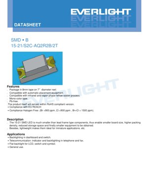
1. Muhtasari wa Bidhaa
The 15-21/S2C-AQ2R2B/2T is a surface-mount device (SMD) LED utilizing AlGaInP (Aluminum Gallium Indium Phosphide) semiconductor technology, emitting a bright orange light. This component is specifically designed for high-density PCB applications where space and weight are critical constraints. Its compact form factor significantly reduces board size and equipment volume compared to traditional lead-frame type LEDs.
该 LED 以 8mm 载带包装,卷绕在直径为 7 英寸的卷盘上,完全兼容自动化贴片组装设备。它是单色类型,符合无铅、RoHS、欧盟 REACH 和无卤素法规(Br <900 ppm,Cl <900 ppm,Br+Cl < 1500 ppm)。该器件适用于红外和气相回流焊接工艺。
2. Detailed Technical Parameters
2.1 Absolute Maximum Ratings
These ratings define the limits beyond which permanent damage to the device may occur. Operation under these conditions is not guaranteed.
- Reverse Voltage (VR):5 V. Exceeding this voltage under reverse bias may cause junction breakdown.
- Continuous Forward Current (IF):25 mA. The maximum DC current for reliable operation.
- Peak Forward Current (IFP):60 mA. This is only permitted under pulse conditions with a duty cycle of 1/10 and a frequency of 1 kHz. It must not be used for continuous operation.
- Power Dissipation (Pd):60 mW. The maximum power the package can dissipate at an ambient temperature (Ta) of 25°C. This value decreases with increasing temperature.
- Electrostatic Discharge (ESD) Human Body Model (HBM):2000 V. This indicates the device's sensitivity to static electricity. Proper ESD handling procedures must be followed.
- Operating Temperature (Topr):-40°C to +85°C. The specified ambient temperature range over which the device is designed to operate.
- Storage Temperature (Tstg):-40°C to +90°C.
- Soldering Temperature:This device can withstand reflow soldering with a peak temperature of 260°C for up to 10 seconds, or hand soldering at 350°C per terminal for up to 3 seconds.
2.2 Electro-Optical Characteristics
Isipokuwa imeelezwa vinginevyo, vigezo hivi vinapimwa chini ya hali za kawaida za majaribio Ta=25°C na IF=20 mA. Zinafafanua utendaji wa mwanga na umeme wa LED.
- Nguvu ya Mwangaza (Iv):Anuwai kutoka 90.0 mcd (kiwango cha chini) hadi 180.0 mcd (kiwango cha juu), na uvumilivu wa kawaida wa ±11%. Hii ni mwangaza unaohisiwa wa chanzo cha mwanga.
- Pembe ya Mtazamo (2θ1/2):Thamani ya kawaida ni digrii 130. Hii ni pembe kamili wakati nguvu ya mwangaza ni nusu ya nguvu ya digrii 0 (mhimili).
- Urefu wa Wimbi la Kilele (λp):Thamani ya kawaida ni 611 nm. Urefu wa wimbi wakati usambazaji wa nguvu ya wigo unafikia thamani yake ya juu zaidi.
- Wavelength kuu (λd):Inachukua anuwai kutoka 600.5 nm hadi 612.5 nm. Hii ndiyo urefu wa wimbi mmoja unaolingana zaidi na rangi inayohisiwa ya LED, na uvumilivu wa ±1 nm.
- Upana wa wigo (Δλ):Thamani ya kawaida ni 17 nm. Upana wa wigo katika nusu ya kiwango cha juu zaidi (upana wa nusu ya kiwango cha juu).
- Voltage ya mbele (VF):Katika 20 mA, inachukua anuwai kutoka 1.75 V (kiwango cha chini) hadi 2.35 V (kiwango cha juu), na uvumilivu wa ±0.1V.
- Mkondo wa nyuma (IR):Upeo wa 10 μA wakati voltage ya nyuma (VR) ya 5V inatumika. Kifaa hiki hakikusudiwa kufanya kazi katika upendeleo wa nyuma.
3. Binning System Description
To ensure color and brightness consistency in production, LEDs are sorted into different bins based on key parameters. Model 15-21/S2C-AQ2R2B/2T includes bin codes (A, Q2, R2, B).
3.1 Kugawanya Kwa Nguvu ya Mwanga
LEDs are classified based on their luminous intensity measured at IF=20mA.
- Q2 Bin:90.0 mcd to 112.0 mcd
- R1 bin:112.0 mcd to 140.0 mcd
- R2 bin:140.0 mcd to 180.0 mcd
The "R2" in the model number indicates that the device belongs to the highest brightness bin of this series.
3.2 Kugawanya Kwa Wimbi Kuu
LEDs are sorted according to their dominant wavelength to control the hue.
- D8 bin:600.5 nm to 603.5 nm
- D9 bin:603.5 nm to 606.5 nm
- D10 bin:606.5 nm to 609.5 nm
- D11 bin:609.5 nm hadi 612.5 nm
"A" kwenye modeli inaweza kuwa inalingana na moja ya safu hizi za urefu wa wimbi (kwa mfano, kwa rangi ya machungwa ya kawaida, inaweza kuwa D10 au D11).
3.3 Kugawanya Kwa Voltage ya Mbele
Kugawanya kwa voltage ya mbele husaidia kubuni saketi thabiti za kuendesha sasa.
- Kundi 0:1.75 V hadi 1.95 V
- Kundi 1:1.95 V hadi 2.15 V
- Daraja 2:2.15 V hadi 2.35 V
"B" kwenye nambari ya mfano inawakilisha daraja la voltage ya mbele.
4. Uchambuzi wa Mkunjo wa Utendaji
Mwongozo wa vipimo hutoa mikunjo kadhaa ya sifa, muhimu kwa kuelewa tabia ya LED chini ya hali tofauti za uendeshaji.
4.1 Uwiano wa Nguvu ya Mwanga vs. Mkondo wa Mbele
Mkunjo unaonyesha kuwa mwazao wa mwanga haufuati uwiano wa mstari sawa na mkondo. Katika mikondo ya juu, kutokana na kupungua kwa ufanisi na athari za joto, mwazao wa mwanga huongezeka kwa kiwango cha chini ya mstari. Kuendesha kwa mkondo unaozidi sana 20mA inayopendekezwa kunaweza kusababisha faida ya mwangaza kupungua na kufupisha maisha ya taa.
4.2 Uwiano wa Nguvu ya Mwanga vs. Joto la Mazingira
Uzito wa mwangaza hupungua kadiri joto la mazingira linavyoongezeka. Hii ni sifa ya LED ya semikondukta. Mkunjo huu humwezesha mbuni kukadiria upotezaji wa mwangaza katika mazingira ya joto la juu, jambo muhimu kwa matumizi kama vile dashibodi za magari.
4.3 Mkunjo wa Kupunguza Mkondo wa Mbele
Mchoro huu unafafanua uhusiano kati ya mkondo wa juu unaoruhusiwa wa mbele unaoendelea na joto la mazingira. Kadiri joto linavyoongezeka, ni lazima kupunguza mkondo wa juu ili kukaa ndani ya kikomo cha nguvu ya kifaa na kuzuia kukosa udhibiti wa joto.
4.4 Voltage ya Mbele vs. Mkondo wa Mbele
Mstari huu wa IV (sasa-voltage) unaonyesha uhusiano wa kielelezo wa kawaida wa diode. Voltage huongezeka kwa logariti ya sasa. Mstari huu ni muhimu sana kwa kubuni upinzani wa kuzuia sasa au kiendeshi cha sasa thabiti.
4.5 Radiation Pattern and Spectral Distribution
Mchoro wa mionzi (mchoro wa kuratibu polar) unaonyesha wazi pembe ya mtazamo ya digrii 130. Mchoro wa usambazaji wa wigo unathibitisha umonokromia wa AlGaInP LED, ukiwaonyesha kilele kimoja karibu na 611 nm, na upana wa nusu ya kilele wa kawaida wa 17 nm.
5. Mechanical and Packaging Information
5.1 Package Dimensions
15-21 SMD LED hutumia ufungaji mstatili mwembamba. Vipimo muhimu (kwa mm, isipokuwa imeelezwa, uvumilivu ni ±0.1mm) ni pamoja na urefu wa jumla, upana na urefu. Buku la maelezo hutoa mchoro wa kina unaoonyesha eneo la chipi, umbo la lenzi na fremu ya waya. Alama ya cathode imewekwa wazi kwenye ufungaji ili kutambua mwelekeo sahihi wa polarity wakati wa kukusanyika.
5.2 Polarity Identification
Upeo sahihi ni muhimu sana. Kutumia voltage ya kinyume zaidi ya 5V kutaiharibu LED mara moja. Kifurushi kina alama ya wazi ya cathode (kawaida ni nukta ya kijani, mfuo, au kona iliyokatwa) kama inavyoonyeshwa kwenye mchoro wa vipimo. Buni lazima ahakikhishe mpangilio wa pedi za PCB unalingana na mwelekeo huu.
6. Mwongozo wa Uchomaji na Usanikishaji
6.1 Mkunjo wa Uchomaji wa Reflow
Imebainisha mkunjio wa kuunganisha kwa reflux isiyo na risasi:
- Joto la awali:150–200°C, kwa sekunde 60–120.
- Time Above Liquidus (TAL):Above 217°C for 60–150 seconds.
- Peak Temperature:Maximum 260°C, hold time up to 10 seconds.
- Ramp-up Rate:Maximum 6°C/second.
- Time Above 255°C:Maximum 30 seconds.
- Kasi ya kupoza:Kiwango cha juu cha 3°C/s.
6.2 Uchomaji wa Mikono
Ikiwa ni lazima kufanya kulehemu kwa mkono, uwe mwangalifu sana:
- Tumia chuma cha kulehemu chenye joto la ncha chini ya 350°C.
- Muda wa kugusa kwa kila terminal uwe mdogo hadi sekunde 3.
- Tumia chuma cha kulehemu chenye nguvu ya kiwango cha 25W au chini.
- Kwa kila terminali, weka muda wa angalau sekunde 2 kati ya kulehemu.
6.3 Uhifadhi na Uvumilivu wa Unyevu
LED hufungwa kwenye mfuko wa kizuizi cha unyevu ulio na draya.
- Usifungue mfuko kabla ya kuwa tayari kutumia.
- Baada ya kufungua, LED zisizotumiwa zinapaswa kuhifadhiwa katika mazingira ya ≤30°C na unyevu wa jamaa ≤60%.
- "Maisha ya kiwanda" ya mfuko baada ya kufunguliwa ni saa 168 (siku 7).
- Ikiwa muda wa mfiduo umepita au kiashiria cha kikaushi kimebadilisha rangi, inahitajika kuokwa kwa 60 ±5°C kwa saa 24 kabla ya kuchomelea reflow, ili kuondoa unyevu uliovutwa na kuzuia uharibifu wa "popcorn" wakati wa mchakato wa juu-joto wa kuchomelea.
6.4 Mambo Muhimu ya Kuzingatia
- Kizuizi cha Mkondo:Lazima utumie kizuizi cha nje cha mkondo. Tabia ya kielelezo V-I ya LED inamaanisha mabadiliko madogo ya voltage yatasababisha mabadiliko makubwa ya mkondo, bila kizuizi kutaangamiza mara moja.
- Mkazo wa Mitambo:Epuka kutumia mkazo kwenye mwili wa LED wakati wa kuchomelea au matumizi ya mwisho. Usipotoshe PCB baada ya kukusanyika.
- Ukarabati:Haipendekezi kabisa kufanya ukarabati baada ya kulehemu. Ikiwa ni lazima kabisa, tumia chuma cha kulehemu chenye vichwa viwili ili kuwasha vituo vyote viwili kwa wakati mmoja na kuinua kipengele kwa usawa, ili kuepuka kuharibika kwa pedi. Baada ya jaribio lolote la ukarabati, thibitisha utendaji wa LED.
7. Habari ya Ufungaji na Uagizaji
7.1 Vipimo vya Reel na Tape Carrier
Kifaa hiki kinapatikana katika mfumo wa ukanda wenye matuta, umefungwa kwenye reeli yenye kipenyo cha inchi 7 (178mm).
- Upana wa Ukanda wa Kubeba:8 mm.
- Umbali wa Mfuko:Tazama mchoro wa vipimo.
- Idadi kwa kila mfuko:Vipande 2000.
7.2 Maelezo ya Lebo
Lebo ya mfuko inajumuisha maelezo muhimu ya kufuatilia na utumiaji sahihi:
- CPN:Nambari ya Bidhaa ya Mteja.
- P/N:Nambari ya Bidhaa ya Mzalishaji (mfano, 15-21/S2C-AQ2R2B/2T).
- QTY:Idadi ya Ufungashaji.
- CAT:Ngazi ya Nguvu ya Mwanga (mfano, R2).
- HUE:Ngazi ya Chroma/Wavelength Kuu (mfano, A).
- REF:Forward voltage grade (e.g., B).
- LOT No:Manufacturing lot number for traceability.
8. Mapendekezo ya Utumiaji
8.1 Mandhari ya Kawaida ya Utumiaji
- Automotive Interior:Backlighting for dashboard instruments, switches, and control panels.
- Vifaa vya Mawasiliano:Viashiria vya hali na taa za nyuma za kibodi katika simu na mashine za faksi.
- Elektroniki za Matumizi:Mwanga wa nyuma wa gorofa, taa za kuwasha/zima, na viashiria vya alama kwa skrini ndogo za LCD.
- Kiashiria cha Jumla:Matumizi yoyote yanayohitaji kiashiria cha hali chenye ukubwa mdogo, mkali na rangi ya machungwa.
8.2 Kuzingatia Katika Ubunifu
- Saketi ya Kuendesha:Daima tumia upinzani wa mfululizo au kiendeshi cha mkondo wa kudumu. Tumia fomula R = (Vsupply - VF) / IF kuhesabu thamani ya upinzani, ambapo VF inapaswa kuchaguliwa thamani ya kiwango cha juu zaidi (2.35V) ili kuhakikisha muundo ni thabiti.
- Usimamizi wa Joto:Ingawa kifuniko ni kidogo, ikiwa kifaa kinatumika karibu na mkondo wa juu zaidi au halijoto ya mazingira ya juu, hakikisha eneo la kutosha la shaba la PCB au mashimo ya kupoza joto, kwani joto linaweza kupunguza mwanga unaotolewa na kipindi cha maisha.
- Muundo wa Kioo:Pembe ya mtazamo ya digrii 130 hutoa boriti ya mwanga pana. Ikiwa unahitaji mwanga uliolengwa zaidi, huenda ikahitaji lenzi ya nje au bomba la kuongoza mwanga.
- Ulinzi wa ESD:Hata kama kifaa kina kiwango cha HBM cha 2kV, ikiwa LED iko mahali ambapo mtumiaji anaweza kugusa, unapaswa kutekeleza ulinzi wa ESD kwenye mistari ya ingizo.
9. Ulinganisho wa Kiufundi na Tofauti
Ikilinganishwa na LED za zamani za mashimo au vifurushi vikubwa vya SMD, 15-21 ina faida dhahiri:
- Ukubwa na Uzito:Vifurushi vyake vidogo vinaruhusu msongamano mkubwa wa kufurushia na bidhaa za mwisho nyepesi, jambo muhimu kwa vifaa vya kubebebwa na vidogo.
- Uwiano wa Automatiki:Ufurushaji wa mkanda umeboreshwa kwa usanikishaji wa automatiki wa kasi ya juu, na hupunguza gharama za utengenezaji.
- Utendaji:Ikilinganishwa na teknolojia ya zamani, matumizi ya nyenzo za AlGaInP hutoa ufanisi wa juu wa kutolea mwanga katika anuwai ya wigo wa machungwa/nyekundu.
- Uzingatiaji:Imejengwa ndani kikamilifu kufuata kanuni za kisasa za mazingira (RoHS, halojeni, REACH), ikirahisisha mchakato wa ushikamilifu wa bidhaa za mwisho.
10. Maswali Yanayoulizwa Mara kwa Mara (Kulingana na Vigezo vya Kiufundi)
10.1 Ni thamani gani ya upinzani ninapaswa kutumia wakati ninatumia chanzo cha umeme cha 5V?
Kwa kutumia voltage ya mbele ya juu zaidi ya daraja la 2 (2.35V) na sasa iliyopendekezwa (20mA): R = (5V - 2.35V) / 0.020A = 132.5 ohms. Thamani ya kawaida iliyo karibu zaidi ya 130 ohms au 150 ohms inafaa. Hakikisha kuthibitisha sasa halisi katika mzunguko.
10.2 Je, naweza kutumia 30mA kuendesha LED hii ili kupata mwangaza wa juu zaidi?
Hapana. Kikomo kamili cha juu zaidi cha sasa endelevu ya mbele (IF) ni 25 mA. Kuendesha kwa 30 mA kunazidi kikomo hiki, ambacho kitapunguza kwa kiasi kikubwa kuaminika na maisha ya huduma, na kunaweza kusababisha kushindwa mara moja. Tumia sasa ya kilele (msukumo wa 60mA) kwa uwiano mdogo sana wa kazi tu ikiwa ni lazima.
10.3 Kwa nini mwangaza hupungua wakati bodi ya mzunguko inapokua moto?
Hii ni sifa ya msingi ya semikondukta ya LED, kama inavyoonyeshwa kwenye mkunjo wa "Uwiano wa Ukali wa Mwanga dhidi ya Joto la Mazingira". Ongezeko la joto linaongeza mchanganyiko usio na mionzi ndani ya semikondukta, na hivyo kupunguza ufanisi. Usanifu mzuri wa joto unaweza kupunguza athari hii.
10.4 Mfuko ulifunguliwa mwezi mmoja uliopita. Bado naweza kutumia LED hizi?
Hapana bila kuchukua tahadhari. Kiwango cha Unyeti wa Unyevunyevu kinahitaji LED zitumike ndani ya saa 168 (siku 7) baada ya kufunguliwa kwa mfuko. Ikiwa muda huu umepita, ni lazima LED zikaushwe kwa 60°C kwa saa 24 kabla ya kufanywa upya wa kulehemu ili kuondosha unyevunyevu uliokamatiwa na kuzuia mgawanyiko wa ndani wakati wa mchakato wa juu-joto wa kulehemu.
11. Usanifu Halisi na Mifano ya Matumizi
Mfano: Kusimba Paneli ya Kiashiria cha Hali
Mbuni anaanzisha paneli ya udhibiti yenye viashiria 20 vya hali vya rangi ya machungwa. Walichagua 15-21/S2C-AQ2R2B/2T kwa sababu ya mwangaza wake wa juu (kiwango cha R2) na ukubwa wake mwembamba.
- Ubunifu wa Saketi:Kutumia reli ya kawaida ya umeme ya 5V. Kwa kutumia thamani ya VF ya 2.35V, upinzani wa kikomo wa 150 ohms ulichaguliwa kwa kila LED, ukizalisha mkondo wa takriban 17.7mA, salama chini ya kiwango cha juu cha 25mA.
- Mpangilio wa PCB:Ukubwa mwembamba wa kifurushi uliruhusu LED zote 20 kupangwa kwenye safu moja. Alama ya cathode kwenye mpangilio wa pedi ililinganishwa wazi na mchoro wa kifurushi, kuzuia makosa ya usanikishaji.
- Uzalishaji:Ufungaji wa mkanda wa mfumo wa roll uliruhusu mkusanyaji wa PCB kutumia mashine ya kiotomatiki ya kuweka vipande, kuhakikisha usakinishaji wa haraka, sahihi na thabiti wa vipengele vyote 20.
- Matokeo:Paneli hii ina viashiria vya mwanga vya machungwa yaliyo sawa na yenye mwangaza, rangi (shukrani kwa kiwango cha wavelength) na mwangaza (shukrani kwa kiwango cha nguvu) zikiwa sawa, uzalishaji ukiwa wa ufanisi na unaoaminika.
12. Utangulizi wa Kanuni
15-21 LED inategemea nyenzo za semiconductor za AlGaInP (aluminiumi-galliumi-indiamu-fosforasi). Wakati voltage chanya inatumika kwenye kiunganishi p-n, elektroni na mashimo huingizwa kwenye eneo lenye ufanisi. Muunganiko wao hutoa nishati kwa njia ya fotoni (mwanga). Muundo maalum wa aloi ya AlGaInP huamua nishati ya pengo la bendi, ambayo inafafanua moja kwa moja wavelength (rangi) ya mwanga unaotolewa—kwa mfano huu, machungwa yenye mwangaza (takriban 611 nm). Lensi ya epoksi hufunga chip ya semiconductor, hutoa ulinzi wa kimitambo, na huunda muundo wa pato la mwanga ili kufikia angle maalum ya maono ya digrii 130.
13. Mwelekeo wa Maendeleo
Maendeleo ya SMD LED kama 15-21 yanafuata mwelekeo muhimu kadhaa wa tasnia:
- Kupunguzwa kwa Ukubwa:Ukubwa wa ufungashaji unaendelea kupungua (mfano, kutoka 0603 hadi 0402 hadi 0201 vipimo vya metri), ili kuwezesha vifaa vidogo vya elektroniki.
- Uboreshaji wa ufanisi:Uboreshaji endelevu wa ukuaji wa epitaksi na usanifu wa chipi husababisha ufanisi mkubwa wa mwanga (pato zaidi la mwanga kwa kila watt), na hivyo kupunguza matumizi ya nguvu na mzigo wa joto.
- Uimarishaji wa kuegemea:Uboreshaji wa nyenzo za ufungaji na teknolojia ya kushikilia chipi huleta maisha marefu ya uendeshaji na utendaji bora chini ya hali ngumu (joto la juu, unyevu mwingi).
- Uainishaji wa hali ya juu:Uvumilivu madhubuti zaidi wa uainishaji wa rangi (wavelength) na flux ya mwanga unakuwa kiwango, unaosukumwa na matumizi yanayohitaji uthabiti wa juu wa rangi (kama skrini za rangi kamili na makundi ya taa za magari).
- Ujumuishaji:Mwelekeo wa kuunganisha chipi nyingi za LED (RGB, au nyeupe + rangi) kwenye ufungaji mmoja, au kuunganisha IC ya udhibiti ili kufikia moduli ya "LED akili".
Ufafanuzi wa Istilahi za Vipimo vya LED
Maelezo kamili ya istilahi za kiteknolojia ya LED
I. Viashiria Muhimu vya Utendaji wa Mwangaza na Umeme
| Istilahi | Kipimo/Uwakilishi | Maelezo ya kawaida | Kwa Nini Ni Muhimu |
|---|---|---|---|
| Ufanisi wa Mwanga (Luminous Efficacy) | lm/W (lumen/watt) | Kiasi cha mwanga kinachotolewa kwa kila kitengo cha nishati ya umeme, thamani ya juu zaidi inaonyesha matumizi bora ya nishati. | Huamua moja kwa moja kiwango cha ufanisi wa nishati cha taa na gharama za umeme. |
| Mtiririko wa Mwanga (Luminous Flux) | lm (lumen) | Jumla ya kiasi cha mwanga kinachotolewa na chanzo cha mwanga, kinachojulikana kwa kawaida kama "mwangaza". | Huamua kama taa inatosha kuwa na mwangaza. |
| Pembe ya Kuona Mwanga (Viewing Angle) | ° (digrii), k.m. 120° | Pembe ambapo nguvu ya mwanga hupungua hadi nusu, huamua upana wa boriti ya mwanga. | Huathiri eneo la mwangaza na usawa wake. |
| Joto la rangi (CCT) | K (Kelvin), k.m. 2700K/6500K | Joto la rangi ya mwanga, thamani ya chini inaelekea manjano/joto, thamani ya juu inaelekea nyeupe/baridi. | Huamua mazingira ya taa na matumizi yanayofaa. |
| Kielelezo cha uonyeshaji rangi (CRI / Ra) | Unitless, 0–100 | The ability of a light source to reproduce an object's true colors; Ra≥80 is considered good. | Affects color fidelity; used in high-demand places like shopping malls and art galleries. |
| Color Tolerance (SDCM) | MacAdam ellipse steps, e.g., "5-step" | A quantitative indicator of color consistency; a smaller step number indicates better color consistency. | Kuhakikisha hakuna tofauti ya rangi kati ya taa za kundi moja. |
| Wavelength Kuu (Dominant Wavelength) | nm (nanomita), k.m. 620nm (nyekundu) | Thamani ya wavelength inayolingana na rangi ya LED zenye rangi. | Huamua hue ya LED za rangi moja kama nyekundu, manjano, kijani, n.k. |
| Usambazaji wa Wigo (Spectral Distribution) | Mkunjo wa Urefu wa Mawimbi dhidi ya Ukubwa | Inaonyesha usambazaji wa ukubwa wa mwanga unaotolewa na LED katika urefu wa mawimbi tofauti. | Huathiri uhalisi wa kuonyesha rangi na ubora wa rangi. |
II. Vigezo vya Umeme
| Istilahi | Ishara | Maelezo ya kawaida | Mazingatio ya Ubunifu |
|---|---|---|---|
| Voltage ya Mbele (Forward Voltage) | Vf | Voltage ya chini inayohitajika ili LED iwashwe, kama "kizingiti cha kuanzisha". | Voltage ya chanzo cha usukumaji lazima iwe ≥ Vf, voltage inajumlishwa wakati LED nyingi zimeunganishwa mfululizo. |
| Mkondo wa Mbele (Forward Current) | If | The current value that makes the LED emit light normally. | Constant current drive is often used, as current determines brightness and lifespan. |
| Maximum Pulse Current | Ifp | The peak current that can be withstood for a short time, used for dimming or flashing. | Pulse width and duty cycle must be strictly controlled, otherwise overheating damage will occur. |
| Reverse Voltage | Vr | The maximum reverse voltage an LED can withstand; exceeding it may cause breakdown. | The circuit must be protected against reverse connection or voltage surges. |
| Thermal Resistance | Rth (°C/W) | Upinzani wa joto kutoka kwenye chip hadi kwenye sehemu ya kuunganishia, thamani ya chini inaonyesha usambazaji bora wa joto. | Upinzani wa juu wa joto unahitaji muundo wa nguvu zaidi wa usambazaji wa joto, vinginevyo joto la kiungo litaongezeka. |
| ESD Immunity | V (HBM), k.m. 1000V | Uwezo wa kukabiliana na mshtuko wa umeme wa tuli, thamani ya juu inaonyesha uwezo mkubwa wa kuepusha uharibifu kutokana na umeme wa tuli. | Katika uzalishaji, ni muhimu kuchukua hatua za kinga dhidi ya umeme wa tuli, hasa kwa LED zenye usikivu mkubwa. |
III. Udhibiti wa Joto na Uthabiti
| Istilahi | Viashiria Muhimu | Maelezo ya kawaida | Athari |
|---|---|---|---|
| Joto la Kiungo (Junction Temperature) | Tj (°C) | Joto halisi la kufanya kazi ndani ya chip ya LED. | Kila kupungua kwa 10°C, maisha yanaweza kuongezeka mara mbili; joto la juu sana husababisha kupungua kwa mwanga, na mabadiliko ya rangi. |
| Kupungua kwa Mwanga (Lumen Depreciation) | L70 / L80 (saa) | Muda unaohitajika kwa mwangaza kupungua hadi 70% au 80% ya thamani ya awali. | Kufafanua moja kwa moja "maisha ya huduma" ya LED. |
| Kiwango cha Kudumisha Lumeni (Lumen Maintenance) | % (k.m. 70%) | Asilimia ya mwangaza uliobaki baada ya kutumia kwa muda fulani. | Inaonyesha uwezo wa kudumisha mwangaza baada ya matumizi ya muda mrefu. |
| Mabadiliko ya Rangi (Color Shift) | Δu′v′ au MacAdam Ellipse | Kiwango cha mabadiliko ya rangi wakati wa matumizi. | Inaathiri ufanisi wa rangi katika mazingira ya taa. |
| Uzeefu wa joto (Thermal Aging) | Kupungua kwa utendaji wa nyenzo | Uharibifu wa nyenzo za ufungaji unaosababishwa na joto la juu kwa muda mrefu. | Inaweza kusababisha kupungua kwa mwangaza, mabadiliko ya rangi, au kushindwa kwa mzunguko wazi. |
IV. Ufungaji na Nyenzo
| Istilahi | Common Types | Maelezo ya kawaida | Characteristics and Applications |
|---|---|---|---|
| Encapsulation Types | EMC, PPA, Ceramic | The housing material that protects the chip and provides optical and thermal interfaces. | EMC offers good heat resistance and low cost; ceramic provides superior heat dissipation and long lifespan. |
| Muundo wa Chip | Usanidi wa Kawaida, Usanidi wa Kugeuzwa (Flip Chip) | Njia ya Kupangia Elektrodi za Chip. | Usanidi wa Kugeuzwa una ubora bora wa kupoza joto na ufanisi wa juu wa mwanga, unaofaa kwa nguvu ya juu. |
| Mipako ya Fosforesenti | YAG, Siliketi, Nitraidi | Coated on the blue LED chip, partially converted to yellow/red light, mixed to form white light. | Different phosphors affect luminous efficacy, color temperature, and color rendering. |
| Lens/Optical Design | Flat, microlens, total internal reflection | Optical structure on the encapsulation surface, controlling light distribution. | Determines the emission angle and light distribution curve. |
V. Udhibiti wa Ubora na Uainishaji
| Istilahi | Yaliyomo ya Uainishaji | Maelezo ya kawaida | Kusudi |
|---|---|---|---|
| Uainishaji wa Flux ya Mwanga | Msimbo kama vile 2G, 2H | Pangilia kulingana na kiwango cha mwangaza, kila kikundi kina thamani ya chini/ya juu ya lumen. | Hakikisha mwangaza ni sawa kwa bidhaa za kundi moja. |
| Kugawa kwa voltage | Msimbo kama vile 6W, 6X | Kugawa kwa anuwai ya voltage ya mbele. | Ili kurahisisha ulinganifu wa chanzo cha kuendesha na kuboresha ufanisi wa mfumo. |
| Kugawa kwa rangi | 5-step MacAdam Ellipse | Group by color coordinates to ensure colors fall within an extremely narrow range. | Ensure color consistency to avoid color variation within the same luminaire. |
| CCT (Correlated Color Temperature) Sorting/Binning | 2700K, 3000K, etc. | Group by CCT, with each group having a corresponding coordinate range. | Kukidhi mahitaji ya joto la rangi katika hali mbalimbali. |
VI. Uchunguzi na Uthibitisho
| Istilahi | Kigezo/Uchunguzi | Maelezo ya kawaida | Maana |
|---|---|---|---|
| LM-80 | Uchunguzi wa Kudumisha Lumen | Long-term illumination under constant temperature conditions, recording brightness attenuation data. | Used to estimate LED lifespan (combined with TM-21). |
| TM-21 | Life Projection Standard | Estimating lifespan under actual usage conditions based on LM-80 data. | Providing scientific lifespan prediction. |
| IESNA Standard | Illuminating Engineering Society Standard | Inashughulikia mbinu za upimaji wa mwanga, umeme na joto. | Msingi unaokubalika kitaalamu wa upimaji. |
| RoHS / REACH | Uthibitisho wa usawa na mazingira. | Hakikisha bidhaa hazina vitu hatari (kama risasi, zebaki). | Masharti ya kuingia kwenye soko la kimataifa. |
| ENERGY STAR / DLC | Uthibitisho wa Ufanisi wa Nishati | Uthibitisho wa ufanisi na utendaji kazi kwa bidhaa za taa. | Hutumiwa mara nyingi katika miradi ya ununuzi wa serikali na ruzuku, kuimarisha ushindani wa soko. |