目录
- 1. 产品概述
- 1.1 核心特性与优势
- 1.2 目标应用
- 2. 技术规格与客观解读
- 2.1 绝对最大额定值
- 2.2 光电特性 (Ta=25°C, IF=5mA)
- 3. 分档系统说明
- 3.1 发光强度分档
- 3.2 主波长(颜色)分档
- 3.3 正向电压分档
- 4. 性能曲线分析
- 5. 机械与封装信息
- 5.1 封装尺寸
- 5.2 推荐PCB封装
- 6. 焊接与组装指南
- 6.1 回流焊温度曲线
- 6.2 手工焊接
- 6.3 存储与湿度敏感性
- 7. 封装与订购信息
- 7.1 载带与卷盘规格
- 7.2 标签信息
- 8. 应用设计注意事项
- 8.1 电流限制
- 8.2 热管理
- 8.3 ESD与操作处理
- 9. 技术对比与差异化分析
- 10. 常见问题解答 (FAQ)
- 11. 设计应用案例示例
- 12. 工作原理
- 13. 技术趋势
- LED 规格术语
- 光电性能
- 电气参数
- Thermal Management & Reliability
- Packaging & Materials
- Quality Control & Binning
- Testing & Certification
1. 产品概述
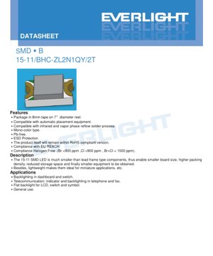
15-11/BHC-ZL2N1QY/2T是一款紧凑型表面贴装蓝色LED,专为需要高密度元件布局的现代电子应用而设计。该器件采用InGaN(氮化铟镓)半导体技术,可产生典型主波长为468 nm的蓝光。其微型占位面积和薄型设计使其成为空间受限应用的理想选择。
1.1 核心特性与优势
该LED的主要优势源于其SMD(表面贴装器件)封装。它以缠绕在7英寸直径卷盘上的8mm载带形式提供,确保与高速自动化贴片组装设备的兼容性。与通孔元件相比,这显著减少了制造时间和成本。该器件适用于标准的红外和气相回流焊接工艺,与主流的PCB组装技术保持一致。
Key product features include compliance with major environmental and safety standards: it is Pb-free (lead-free), incorporates ESD (Electrostatic Discharge) protection, adheres to the EU REACH regulation, and meets halogen-free requirements (Br <900 ppm, Cl <900 ppm, Br+Cl < 1500 ppm). The product is also designed to remain within RoHS (Restriction of Hazardous Substances) compliant specifications.
其小巧尺寸(约1.6mm x 0.8mm x 0.6mm)有助于显著节省电路板空间、提高封装密度并减小终端产品尺寸。其轻量化结构进一步支持其在微型和便携式应用中的使用。
1.2 目标应用
这款蓝色LED适用于多种指示灯和背光功能。常见的应用领域包括汽车仪表板和开关的背光、电话和传真机等通信设备中的状态指示灯和键盘背光、LCD面板的平面背光、开关照明,以及需要清晰、明亮蓝色信号的通用指示灯用途。
2. 技术规格与客观解读
2.1 绝对最大额定值
这些额定值定义了应力极限,超过此极限可能对器件造成永久性损坏。它们不适用于正常操作。
- 反向电压 (VR): 5V。在反向偏置中超过此电压可能导致结击穿。
- 连续正向电流 (IF): 10 mA。这是保证长期可靠运行的最大直流电流。
- 峰值正向电流 (IFP): 100 mA(在1/10占空比,1 kHz条件下)。这允许短暂的高电流脉冲,适用于多路复用或脉冲信号传输,但必须控制平均功率。
- 功耗 (Pd): 40 mW。这是最大允许功率损耗 (VF * IF在25°C环境温度下。在更高温度下需要降额使用。
- ESD耐受能力(HBM): 2000V。为操作过程中的静电放电提供一定程度的保护,但仍建议遵循正确的ESD防护规程。
- 工作温度(Topr): -40°C 至 +85°C。器件功能正常运行的环境温度范围。
- 存储温度(Tstg): -40°C 至 +90°C。
- 焊接温度: 回流焊峰值温度260°C,最长10秒;手工焊接温度350°C,每个端子最长3秒。
2.2 光电特性 (Ta=25°C, IF=5mA)
这些参数定义了LED在标准测试条件下的典型性能。
- 发光强度 (Iv): 14.5 至 36.0 mcd (毫坎德拉)。实际输出已分级(参见第3节)。
- 视角 (2θ1/2): 130度(典型值)。这种宽广的视角是LED透镜设计的特性,提供了广阔的发射模式。
- 峰值波长 (λp): 468 nm(典型值)。这是光谱功率分布达到最大值时的波长。
- 主波长 (λd): 465 至 475 nm。这定义了光的感知颜色,并且也是经过分档的。
- 光谱带宽 (Δλ): 25 nm(典型值)。这是最大强度一半处(半高宽)的发射光谱宽度。
- 正向电压 (VF): 2.70 至 3.20 V。这是在测试电流下LED两端的电压降。此参数经过分档,且在同一档内具有±0.05V的容差。
3. 分档系统说明
为确保量产一致性,LED会按性能等级进行分档。15-11/BHC-ZL2N1QY/2T采用针对发光强度、主波长和正向电压的三维分档系统。
3.1 发光强度分档
分档由代码L2、M1、M2和N1定义,最小光强范围从14.5 mcd到28.5 mcd。型号中的分档代码(例如ZL2中的'N1')规定了保证的最小和最大光输出。发光强度的容差为±11%。N1QY)规定了保证的最小和最大光输出。发光强度的容差为±11%。
3.2 主波长(颜色)分档
波长分为两个代码:'X'(465-470 nm)和'Y'(470-475 nm)。型号中标明了此分档(例如ZL2N1中的'Y')。主波长的指定容差为±1nm。QY)。主波长的指定容差为±1nm。
3.3 正向电压分档
正向电压被分为五个档位,编码为29至33,对应的电压范围从2.70-2.80V到3.10-3.20V。部件号指明了此档位(例如,ZL2N1QY)。同一档位内的容差为±0.05V。
4. 性能曲线分析
虽然提供的文本中未详述具体的图形曲线,但此类LED典型的光电特性通常包括:
- I-V(电流-电压)曲线: 显示了正向电流与正向电压之间的指数关系。对于蓝色InGaN LED,其开启电压通常在2.7-3.2V左右。
- 光强 vs. 正向电流: 在正常工作电流范围内(直至IF),发光强度通常随电流线性增加,但在极高电流下可能因发热导致效率下降。
- 发光强度与环境温度关系: 光输出通常随结温升高而降低。理解这种降额特性对于在高温环境下工作的设计至关重要。
- 光谱分布: 显示各波长相对辐射功率的曲线图,中心波长约为468 nm,半高宽约25 nm。
5. 机械与封装信息
5.1 封装尺寸
该LED的标称本体尺寸为长1.6mm、宽0.8mm、高0.6mm。封装图纸详细规定了LED本体、焊盘以及阴极标记位置的确切尺寸和公差(除非另有说明,否则为±0.1mm)。阴极通过封装上的特定标记来识别,这对于PCB的正确方向至关重要。
5.2 推荐PCB封装
应使用能够适应封装尺寸并允许形成适当焊锡圆角的焊盘图案设计。数据手册中的尺寸图为在PCB CAD软件中创建此封装提供了依据。
6. 焊接与组装指南
6.1 回流焊温度曲线
对于无铅组装,提供了一个推荐的回流焊温度曲线:在150-200°C之间预热60-120秒,液相线(217°C)以上时间为60-150秒,峰值温度不超过260°C且最长持续10秒。最大升温速率不超过6°C/秒,最大降温速率不超过3°C/秒。回流焊接次数不应超过两次。
6.2 手工焊接
正向电流 hand soldering is necessary, the soldering iron tip temperature 必须 be below 350°C, and contact time per terminal 必须 not exceed 3 seconds. A low-power iron (<25W) is recommended. A cooling interval of at least 2 seconds should be allowed between soldering each terminal to prevent thermal stress.
6.3 存储与湿度敏感性
本产品采用内含干燥剂的防潮袋包装。在准备使用元件前,请勿打开包装袋。开封后,LED应储存在温度≤30°C、相对湿度≤60%的环境中。在此条件下的“车间寿命”为1年。若储存时间超过规定或干燥剂显示已吸湿,则需在焊接前进行60±5°C、24小时的烘烤处理。
7. 封装与订购信息
7.1 载带与卷盘规格
LED采用压纹载带包装,具体尺寸在数据手册中规定。每卷包含2000颗。同时提供了卷盘尺寸,以便自动化设备处理。
7.2 标签信息
卷盘标签包含关键信息:客户产品编号(CPN)、制造商零件编号(P/N)、包装数量(QTY),以及光强等级(CAT)、色度/主波长等级(HUE)和正向电压等级(REF)的具体分档代码,连同批号。
8. 应用设计注意事项
8.1 电流限制
关键: 必须串联一个外部限流电阻或恒流驱动器 必须 与LED一起使用。正向电压具有负温度系数,这意味着它会随着结温升高而降低。如果没有电流限制,这可能导致热失控和快速失效(烧毁)。电阻值通过公式 R = (V电源 - VF) / I 计算得出。F.
8.2 热管理
尽管功耗较低(最大40mW),但正确的PCB布局有助于管理结温。确保有足够的铜箔面积连接到LED的散热焊盘(如果有)或阳极/阴极走线,以充当散热器,尤其是在高环境温度或接近最大电流下工作时。
8.3 ESD与操作处理
尽管内置了ESD保护,但在操作和组装过程中仍应遵循标准的ESD预防措施(如佩戴腕带、使用接地工作站和导电泡沫),以防止潜在损伤。
9. 技术对比与差异化分析
15-11封装在小型化与易于操作/制造之间取得了平衡。与更大的SMD LED(例如3528、5050)相比,它能显著节省电路板空间。与更小的芯片级封装(CSP)相比,它通常更容易使用标准SMT工艺进行组装、检测和返修。其130度的宽视角,使其与那些为聚光照明设计的、光束角更窄的LED区分开来。
10. 常见问题解答 (FAQ)
问:如果我的电源是3.0V,我可以不串联电阻直接驱动这个LED吗?
答:不可以。即使电源电压接近典型的VF,VF 的变化(批次间差异和随温度变化)以及电源电压的容差都使得直接连接存在风险。始终需要一个限流机制。
问:峰值波长和主波长有什么区别?
答:峰值波长(λp)是光谱发射最大值对应的物理波长。主波长(λd)是单色光的波长,该单色光与LED的感知颜色相匹配。对于蓝色LED,两者通常非常接近。
问:如何解读部件号'15-11/BHC-ZL2N1QY/2T'?
答:'15-11'是封装代码。'BHC'可能表示颜色(蓝色)和其他属性。'ZL2N1QY'包含分档代码:发光强度(N1)、主波长(Q)和正向电压(Y)。'2T'可能指卷带包装。
11. 设计应用案例示例
场景:薄膜开关面板的背光照明。 多个15-11蓝色LED被放置在面板的半透明图标后方。一个简单的设计会使用5V电源。对于5mA的IF 和3.0V的典型VF ,串联电阻值为 R = (5V - 3.0V) / 0.005A = 400Ω。标准的390Ω或430Ω电阻是合适的。LED可以并联连接,每个LED使用独立的电阻,以确保尽管VF 存在差异,亮度依然均匀。宽广的视角确保了图标区域的均匀照明。
12. 工作原理
该LED基于由InGaN材料制成的半导体p-n结。当施加超过结内建电势的正向电压时,电子和空穴被注入到有源区并在其中复合。在InGaN中,这种复合释放的能量主要以可见光谱蓝色区域的光子(光)形式存在。具体的波长由InGaN合金成分的带隙能量决定。
13. 技术趋势
InGaN技术推动的高效蓝光LED发展是固态照明领域的一项基础性成就,它促成了白光LED(通过荧光粉转换)的诞生,并获得了2014年诺贝尔物理学奖。当前SMD LED的发展趋势持续朝着更高效率(每瓦更多流明)、更小封装内更高的功率密度、更优的显色性以及更严格的分档公差方向发展,以满足显示背光和汽车照明等严苛应用中对性能一致性的要求。
LED 规格术语
LED技术术语完整解释
光电性能
| 术语 | 单位/表示法 | 简单解释 | 重要性 |
|---|---|---|---|
| 光效 | lm/W (流明每瓦) | 每瓦电力产生的光输出,数值越高表示能效越高。 | 直接决定能效等级和电费成本。 |
| 光通量 | lm (流明) | 光源发出的总光量,通常称为“亮度”。 | 决定光线是否足够明亮。 |
| 光束角 | °(度),例如:120° | 光强降至一半时的角度,决定光束宽度。 | 影响照明范围与均匀度。 |
| CCT(色温) | K(开尔文),例如:2700K/6500K | 光的冷暖感,数值越低越偏黄/暖,越高越偏白/冷。 | 决定照明氛围与适用场景。 |
| CRI / Ra | 无量纲,0–100 | 准确呈现物体颜色的能力,Ra≥80为佳。 | 影响色彩真实性,用于商场、博物馆等高要求场所。 |
| SDCM | MacAdam椭圆步数,例如“5步” | 颜色一致性指标,步数越小表示颜色一致性越高。 | 确保同一批次LED的颜色均匀一致。 |
| Dominant Wavelength | nm(纳米),例如620nm(红色) | 对应彩色LED颜色的波长。 | 决定红色、黄色、绿色单色LED的色调。 |
| Spectral Distribution | 波长与强度关系曲线 | 显示各波长上的强度分布。 | 影响显色性和质量。 |
电气参数
| 术语 | 符号 | 简单解释 | 设计考量 |
|---|---|---|---|
| 正向电压 | Vf | 点亮LED所需的最小电压,类似于“启动阈值”。 | 驱动器电压必须≥Vf,串联LED的电压会累加。 |
| 正向电流 | 正向电流 | 正常LED工作时的电流值。 | Usually constant current drive, current determines brightness & lifespan. |
| 最大脉冲电流 | 正向脉冲电流 | 可短时耐受的峰值电流,用于调光或闪烁。 | Pulse width & duty cycle 必须 be strictly controlled to avoid damage. |
| Reverse Voltage | Vr | LED可承受的最大反向电压,超出可能导致击穿。 | 电路必须防止反接或电压尖峰。 |
| 热阻 | Rth (°C/W) | 芯片到焊点的热传递阻力,数值越低越好。 | 高热阻需要更强的散热能力。 |
| ESD抗扰度 | V (HBM),例如:1000V | 抗静电放电能力,数值越高表示越不易受损。 | 生产中需采取防静电措施,特别是对于敏感的LED。 |
Thermal Management & Reliability
| 术语 | 关键指标 | 简单解释 | 影响 |
|---|---|---|---|
| Junction Temperature | 结温 (°C) | LED芯片内部的实际工作温度。 | 每降低10°C,寿命可能延长一倍;温度过高会导致光衰和色偏。 |
| 光通维持率 | L70 / L80 (小时) | 亮度降至初始值70%或80%所需的时间。 | 直接定义LED“使用寿命”。 |
| 光通维持率 | %(例如:70%) | 经过一段时间后保留的亮度百分比。 | 表示长期使用下的亮度保持情况。 |
| Color Shift | Δu′v′ 或麦克亚当椭圆 | 使用过程中的颜色变化程度。 | 影响照明场景中的颜色一致性。 |
| Thermal Aging | 材料降解 | 因长期高温导致的劣化。 | 可能导致亮度下降、颜色变化或开路故障。 |
Packaging & Materials
| 术语 | 常见类型 | 简单解释 | Features & Applications |
|---|---|---|---|
| 封装类型 | EMC, PPA, Ceramic | 封装材料保护芯片,提供光/热界面。 | EMC:耐热性好,成本低;陶瓷:散热更佳,寿命更长。 |
| 芯片结构 | 正装,倒装 | 芯片电极排布。 | 倒装芯片:散热更好,效率更高,适用于大功率。 |
| 荧光粉涂层 | YAG, 硅酸盐, 氮化物 | 覆盖蓝色芯片,将部分蓝光转换为黄/红光,混合成白光。 | 不同的荧光粉影响光效、色温和显色指数。 |
| 透镜/光学元件 | 平面透镜,微透镜,全内反射透镜 | 控制光分布的光学表面结构。 | 决定视角与光分布曲线。 |
Quality Control & Binning
| 术语 | 分档内容。 | 简单解释 | 目的。 |
|---|---|---|---|
| 光通量分档。 | 代码,例如 2G, 2H | 按亮度分组,每组有最小/最大流明值。 | 确保同一批次亮度均匀。 |
| Voltage Bin | 代码,例如 6W, 6X | 按正向电压范围分组。 | 促进司机匹配,提升系统效率。 |
| Color Bin | 5-step MacAdam ellipse | 按色坐标分组,确保色容差范围紧密。 | 保证颜色一致性,避免灯具内部颜色不均。 |
| CCT Bin | 2700K、3000K等色温值 | 按相关色温分组,每组有对应的色坐标范围。 | 满足不同场景的相关色温要求。 |
Testing & Certification
| 术语 | 标准/测试 | 简单解释 | 意义 |
|---|---|---|---|
| LM-80 | 流明维持率测试 | 在恒温条件下进行长期照明,记录亮度衰减。 | 用于(结合TM-21)估算LED寿命。 |
| TM-21 | 寿命估算标准 | 基于LM-80数据估算实际条件下的寿命。 | 提供科学的寿命预测。 |
| IESNA | Illuminating Engineering Society | 涵盖光学、电学、热学测试方法。 | 行业公认的测试基准。 |
| RoHS / REACH | 环境认证 | 确保不含有害物质(铅、汞)。 | 国际市场的准入要求。 |
| ENERGY STAR / DLC | 能效认证 | 照明产品的能效与性能认证。 | 用于政府采购、补贴项目,提升竞争力。 |