目录
- 1. 产品概述
- 技术参数详解
- 2.1 绝对最大额定值
- 2.2 光电特性
- 3. 分档系统说明
- 3.1 光强分档
- 3.2 正向电压分档
- 3.3 色坐标分档
- 4. 性能曲线分析
- 5. 机械与封装信息
- 5.1 封装尺寸
- 5.2 极性标识
- 6. 焊接与组装指南
- 7. 封装与订购信息
- 8. 应用建议
- 8.1 典型应用场景
- 8.2 设计注意事项
- 9. 技术对比与差异化
- 10. 常见问题解答(基于技术参数)
- 11. 实际应用案例
- 12. 工作原理介绍
- 13. 技术趋势
- LED 规格术语
- 光电性能
- 电气参数
- Thermal Management & Reliability
- Packaging & Materials
- Quality Control & Binning
- Testing & Certification
1. 产品概述
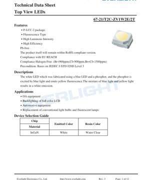
本文档详述了一款高性能白光发光二极管(LED)的规格,该器件采用蓝光LED芯片结合荧光粉涂层技术。器件封装于紧凑的P-LCC-2(塑料引线芯片载体)表面贴装封装内,专为顶视应用设计,其发光方向垂直于安装平面。核心技术涉及蓝光LED激发黄色荧光粉;由此产生的蓝光与黄光混合产生白光发射。此方法是固态光源产生白光的标准技术,在效率和色彩调节方面具有优势。
The LED is characterized by its high luminous intensity and efficiency. It is constructed using lead-free (Pb-free) materials and complies with major environmental regulations including RoHS, EU REACH, and halogen-free standards (Br<900ppm, Cl<900ppm, Br+Cl<1500ppm). The device is preconditioned according to the moisture sensitivity level 3 standard (JEDEC J-STD-020D), indicating its robustness for standard surface-mount assembly processes.
技术参数详解
2.1 绝对最大额定值
设备不得超出这些极限值运行,以防造成永久性损坏。关键额定值包括最大反向电压(VR)为5V,连续正向电流(IF)为30mA,以及在脉冲条件下(1kHz频率下占空比1/10)的峰值正向电流(IFP)为100mA。最大功耗(Pd)为110mW。工作温度范围为-40°C至+85°C,存储温度范围略宽,为-40°C至+90°C。在焊接方面,它能承受峰值温度为260°C持续10秒的回流焊曲线,或350°C持续3秒的手工焊接。其静电放电(ESD)耐受电压为1000V(人体模型)。
2.2 光电特性
关键性能参数是在25°C环境温度和20mA正向电流的标准测试条件下测定的。发光强度(Iv)的典型范围从最小715毫坎德拉(mcd)到最大2240 mcd,规定容差为±11%。视角(2θ1/2)定义为半强度全角,通常为120度,提供宽光束模式。在20mA电流下,正向电压(VF)范围为2.75V至3.65V,容差为±0.05V。当施加5V反向偏压时,反向电流(IR)规定最大为50µA。
3. 分档系统说明
为确保生产一致性,LED会根据关键参数进行分档。这使得设计人员能够选择满足特定应用在亮度和电气特性方面要求的器件。
3.1 光强分档
光输出被分为五个不同的等级:V1 (715-900 mcd)、V2 (900-1120 mcd)、W1 (1120-1420 mcd)、W2 (1420-1800 mcd) 和 BA (1800-2240 mcd)。所有测量均在 IF=20mA 条件下进行。
3.2 正向电压分档
正向电压在总组别“V”下分为三个等级:E5 (2.75-3.05V)、6 (3.05-3.35V) 和 7 (3.35-3.65V)。此分档的容差为 ±0.1V。
3.3 色坐标分档
白光的颜色根据其在 CIE 1931 色品图上的坐标进行精确控制和分档。等级标签(例如 A0-1, A0-2, A0+1, A0+2 等)定义了 x,y 色彩空间中的特定四边形区域。这些坐标的容差为 ±0.01。通常会提供图表在色品图上可视化这些等级,以确保发出的白光落在所需的色温和色调范围内。
4. 性能曲线分析
图形数据能更深入地揭示LED在不同条件下的行为特性。
- 正向电流与正向电压关系曲线(IV曲线): 该曲线展示了电流与电压之间的非线性关系,对于设计限流电路至关重要。
- 相对发光强度与正向电流关系曲线: 此图表明光输出如何随电流增加而增加,通常在较高电流下,由于效率下降,会呈现亚线性增长。
- 相对发光强度与环境温度关系曲线: 这条关键曲线显示了随着结温升高,光输出会下降。理解这种降额特性对于应用中的热管理至关重要。
- 正向电流降额曲线: 该曲线定义了在环境温度变化时,为保持在功耗限制范围内所允许的最大正向电流。
- 光谱分布: 一幅相对强度与波长的关系图,显示了特征性的宽泛黄色荧光粉发射峰与较窄的蓝色LED峰相结合。
- 辐射方向图: 一幅极坐标图,展示了光强度的空间分布,证实了120度的视角。
5. 机械与封装信息
5.1 封装尺寸
P-LCC-2封装有详细的机械图纸,说明了其长度、宽度、高度、引脚尺寸以及推荐的PCB焊盘图形。除非另有说明,所有尺寸均以毫米为单位,标准公差为±0.1mm。该封装具有两个用于电气连接的引脚,并带有清晰的极性指示(通常是一个凹口或标记的阴极)。
5.2 极性标识
标签说明图指示了LED顶部的产品标记如何对应其性能分档:一个代码代表发光强度等级(CAT),一个代表主波长/色度等级(HUE),一个代表正向电压等级(REF)。
6. 焊接与组装指南
The device is suitable for standard SMT assembly lines. The maximum soldering temperature ratings must be strictly adhered to: 260°C peak temperature for 10 seconds during reflow soldering, or 350°C for 3 seconds if hand soldering. The moisture sensitivity level (MSL) is 3, meaning the components are packaged in a moisture-barrier bag with desiccant and have a floor life of 168 hours (1 week) after the bag is opened at factory conditions (<30°C/60%RH).
7. 封装与订购信息
LED以凸纹载带形式提供,适用于自动化贴装。每卷包含2000颗。提供了载带凹槽和整体卷盘的详细尺寸。元件封装在含有干燥剂的密封铝箔防潮袋中运输,外部贴有适当的湿度指示卡和警告标签。
8. 应用建议
8.1 典型应用场景
这款高亮度白光LED适用于多种需要紧凑、高效照明的应用。主要用途包括消费电子和工业面板中全彩液晶显示器(LCD)的背光、办公自动化(OA)设备中的指示灯和状态照明、汽车内饰照明与指示灯,以及作为标牌和装饰照明中传统小型白炽灯泡或荧光灯的替代品。
8.2 设计注意事项
电流驱动: LED是电流驱动器件。必须使用恒流源或与电压源串联的限流电阻,以防止热失控并确保稳定的光输出。设计必须考虑正向电压分级及其随温度的变化。
热管理: 尽管LED效率很高,但其结区会产生热量。过高的温度会降低光输出和寿命。确保PCB提供足够的热缓解,尤其是在以最大电流或接近最大电流驱动时。
光学设计: 120度的视角提供了宽广的漫射光束。如需聚焦光,则需要次级光学元件(透镜、反射器)。水透明树脂颜色适用于LED芯片本身不应着色的应用。
9. 技术对比与差异化
与早期的通孔式白光LED相比,这种SMT P-LCC-2封装在节省电路板空间、适合自动化组装以及可能提供更好的PCB热路径方面具有显著优势。指定的高发光强度分级(W2, BA)提供的性能适合需要小尺寸高亮度的应用。涵盖强度、电压和色度的综合分级系统为设计人员提供了灵活性,可根据成本优化或性能关键型设计选择器件,确保组件内的颜色和亮度一致性。
10. 常见问题解答(基于技术参数)
问:这款LED的典型工作电流是多少?
答:标准测试条件和大多数数据手册规格均以20mA给出。它可以在其绝对最大值30mA连续电流下工作,但光输出和效率应从性能曲线中验证,并且热管理变得更加关键。
问:如何解读色品分档代码(例如,A0+2)?
答:这些代码对应于数据手册中定义的CIE色度图上的特定区域。它们确保白点(相关色温和色调)处于受控范围内。设计人员应选择符合其产品颜色一致性要求的分档。
问:我可以用5V电源直接驱动这款LED吗?
答:不可以,必须有限流机制。其正向电压通常在3.0-3.4V左右。直接连接5V会导致电流过大,超过最大额定值并损坏LED。必须使用串联电阻或恒流驱动器。
11. 实际应用案例
场景:为工业设备设计状态指示面板。 使用多个白色LED照亮半透明图标。为确保亮度均匀,应选用同一光强等级(例如W1)的LED。可以设计一个简单的驱动电路,使用12V电源轨并为每个LED串联一个电阻。电阻值计算公式为 R = (V_电源 - VF_LED) / I_LED。使用等级6的典型正向电压VF=3.2V,期望电流为20mA,则 R = (12V - 3.2V) / 0.02A = 440欧姆(使用标准的470欧姆电阻将产生约18.7mA电流,这是可接受的)。120度的宽视角确保图标照明均匀,无热点。
12. 工作原理介绍
这是一种荧光粉转换型白光LED。其基本光源是一个由氮化铟镓(InGaN)制成的半导体芯片,在正向偏置时发出蓝光(电致发光)。这部分蓝光被覆盖在芯片上的一层掺铈的钇铝石榴石(YAG:Ce)荧光粉涂层部分吸收。荧光粉吸收高能量的蓝色光子,并通过一种称为光致发光的过程重新发射出较低能量的黄光。剩余的未被吸收的蓝光与发射出的黄光混合。人眼将这种光谱成分的组合感知为白光。通过调整荧光粉的成分和厚度,可以精确调节白光的色调或色温。
13. 技术趋势
白光LED的发展一直是固态照明革命的核心。当前趋势聚焦于提高发光效率(每瓦流明数)、改善显色指数(CRI)以获得更自然的光线,以及实现更高的可靠性和更长的使用寿命。荧光粉技术的进步,包括使用量子点或多荧光粉混合物,使得对发射光谱的控制更加精细。同时,在保持或增加光输出的同时实现小型化也是一个发展方向,如微型LED(micro-LED)所示。此外,将控制电子器件直接集成到LED封装中,用于智能照明应用,正成为一个日益增长的发展领域。
LED 规格术语
LED技术术语完整解释
光电性能
| 术语 | 单位/表示法 | 简要说明 | 重要性 |
|---|---|---|---|
| 光效 | lm/W (流明每瓦) | 每瓦电力产生的光输出,数值越高表示能效越高。 | 直接决定能效等级和电费成本。 |
| 光通量 | lm (流明) | 光源发出的总光量,通常称为“亮度”。 | 决定光线是否足够明亮。 |
| 视角 | ° (度),例如:120° | 光强降至一半时的角度,决定光束宽度。 | 影响照明范围和均匀度。 |
| CCT(色温) | K(开尔文),例如 2700K/6500K | 光线的暖/冷色调,数值越低越偏黄/暖,数值越高越偏白/冷。 | 决定照明氛围和适用场景。 |
| CRI / Ra | 无量纲,0–100 | 准确呈现物体颜色的能力,Ra≥80为良好。 | 影响色彩真实性,用于商场、博物馆等高要求场所。 |
| SDCM | MacAdam椭圆步长,例如“5步” | 颜色一致性度量,步长越小表示颜色一致性越好。 | 确保同一批次LED的颜色均匀性。 |
| 主波长 | nm(纳米),例如:620nm(红色) | 对应彩色LED颜色的波长。 | 决定红色、黄色、绿色单色LED的色调。 |
| Spectral Distribution | 波长-强度曲线 | 显示各波长的强度分布。 | 影响显色性和质量。 |
电气参数
| 术语 | 符号 | 简要说明 | 设计考量 |
|---|---|---|---|
| 正向电压 | Vf | 点亮LED所需的最小电压,类似于“启动阈值”。 | 驱动器电压必须≥Vf,串联LED的电压会累加。 |
| 正向电流 | If | 常规LED工作电流值。 | Usually constant current drive, current determines brightness & lifespan. |
| 最大脉冲电流 | Ifp | 短时间内可承受的峰值电流,用于调光或闪烁。 | Pulse width & duty cycle must be strictly controlled to avoid damage. |
| 反向电压 | Vr | LED可承受的最大反向电压,超过此值可能导致击穿。 | 电路必须防止反接或电压尖峰。 |
| 热阻 | Rth (°C/W) | 芯片到焊料的热传递阻力,数值越低越好。 | 高热阻需要更强的散热能力。 |
| ESD Immunity | V (HBM),例如:1000V | 承受静电放电的能力,数值越高意味着越不易受损。 | 生产中需要采取防静电措施,特别是对于敏感的LED。 |
Thermal Management & Reliability
| 术语 | 关键指标 | 简要说明 | 影响 |
|---|---|---|---|
| 结温 | Tj (°C) | LED芯片内部的实际工作温度。 | 每降低10°C,寿命可能延长一倍;温度过高会导致光衰和色偏。 |
| 光通维持率 | L70 / L80 (小时) | 亮度降至初始值70%或80%所需的时间。 | 直接定义了LED的“使用寿命”。 |
| 光通维持 | %(例如:70%) | 经过一段时间后保留的亮度百分比。 | 表示长期使用下的亮度保持能力。 |
| 色漂移 | Δu′v′ 或 MacAdam 椭圆 | 使用过程中颜色变化的程度。 | 影响照明场景中的颜色一致性。 |
| Thermal Aging | Material degradation | 因长期高温导致的劣化。 | 可能导致亮度下降、颜色变化或开路故障。 |
Packaging & Materials
| 术语 | 常见类型 | 简要说明 | Features & Applications |
|---|---|---|---|
| 封装类型 | EMC, PPA, Ceramic | 外壳材料,用于保护芯片,提供光学/热学界面。 | EMC:耐热性好,成本低;Ceramic:散热更佳,寿命更长。 |
| 芯片结构 | 正装,倒装芯片 | 芯片电极排布。 | 倒装芯片:散热更佳,光效更高,适用于大功率。 |
| 荧光粉涂覆 | YAG,硅酸盐,氮化物 | 覆盖蓝光芯片,将部分蓝光转换为黄/红光,混合形成白光。 | 不同的荧光粉影响光效、相关色温和显色指数。 |
| 透镜/光学器件 | 平面、微透镜、全内反射 | 表面控制光分布的光学结构。 | 决定视角和光分布曲线。 |
Quality Control & Binning
| 术语 | 分档内容 | 简要说明 | 目的 |
|---|---|---|---|
| 光通量档位 | 代码,例如 2G, 2H | 按亮度分组,每组有最小/最大流明值。 | 确保同一批次亮度均匀。 |
| Voltage Bin | Code e.g., 6W, 6X | 按正向电压范围分组。 | 便于驱动器匹配,提高系统效率。 |
| Color Bin | 5阶麦克亚当椭圆 | 按色坐标分组,确保范围紧密。 | 保证颜色一致性,避免灯具内部颜色不均。 |
| 色温分级 | 2700K, 3000K 等。 | 按色温分组,每组有对应的坐标范围。 | 满足不同场景的相关色温要求。 |
Testing & Certification
| 术语 | 标准/测试 | 简要说明 | 意义 |
|---|---|---|---|
| LM-80 | Lumen maintenance test | 恒温长期点亮,记录亮度衰减。 | 用于估算LED寿命(结合TM-21)。 |
| TM-21 | 寿命估算标准 | 基于LM-80数据估算实际条件下的寿命。 | 提供科学的寿命预测。 |
| IESNA | Illuminating Engineering Society | 涵盖光学、电气、热学测试方法。 | 行业公认的测试基准。 |
| RoHS / REACH | 环境认证 | 确保不含有害物质(铅、汞)。 | 国际市场的准入要求。 |
| ENERGY STAR / DLC | 能效认证 | 针对照明产品的能效与性能认证。 | 用于政府采购、补贴计划,提升竞争力。 |