Table of Contents
- 1. Product Overview
- 2. Technical Parameters and Specifications
- 2.1 Absolute Maximum Ratings (Ts=25°C)
- 2.2 Electro-Optical Characteristics (Ts=25°C)
- 3. Binning and Ordering System
- 3.1 Product Nomenclature
- 3.2 Correlated Color Temperature (CCT) Binning
- 3.3 Luminous Flux Binning
- 4. Performance Curves and Characteristics
- 4.1 Forward Current vs. Forward Voltage (I-V Curve)
- 4.2 Forward Current vs. Relative Luminous Flux
- 4.3 Spectral Power Distribution
- 4.4 Junction Temperature vs. Relative Luminous Flux
- 5. Mechanical and Package Information
- 5.1 Package Dimensions
- 5.2 Pad Pattern and Stencil Design
- 6. Assembly, Handling, and Storage Guidelines
- 6.1 Moisture Sensitivity and Baking
- 6.2 Reflow Soldering Profile
- 7. Application Notes and Design Considerations
- 7.1 Electrical Drive
- 7.2 Thermal Management
- 7.3 Optical Integration
- 8. Typical Applications
- 9. Frequently Asked Questions (FAQ)
- 10. Technical Comparison and Trends
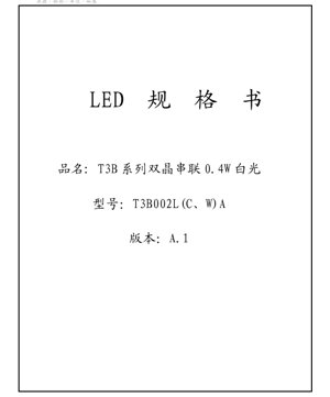
1. Product Overview
The T3B series represents a family of high-efficiency, surface-mount white LEDs housed in the compact 3014 package. This series utilizes a dual-chip configuration connected in series, enabling operation at a higher forward voltage while delivering reliable luminous output. Designed for general lighting applications, backlighting, and indicator uses, these LEDs offer a balance of performance and cost-effectiveness in a small footprint.
The core advantage of this series lies in its series-connected dual-die design. This configuration provides better current distribution and thermal management compared to single-die solutions at similar power levels. The 3014 package (3.0mm x 1.4mm x 0.8mm) is a popular industry standard, ensuring compatibility with existing PCB layouts and pick-and-place assembly equipment.
2. Technical Parameters and Specifications
2.1 Absolute Maximum Ratings (Ts=25°C)
The following parameters define the limits beyond which permanent damage to the device may occur. Operation under these conditions is not guaranteed.
- Forward Current (IF): 80 mA (DC)
- Forward Pulse Current (IFP): 120 mA (Pulse Width ≤10ms, Duty Cycle ≤1/10)
- Power Dissipation (PD): 544 mW
- Operating Temperature (Topr): -40°C to +80°C
- Storage Temperature (Tstg): -40°C to +80°C
- Junction Temperature (Tj): 125°C
- Soldering Temperature (Tsld): 230°C or 260°C for 10 seconds (reflow soldering)
2.2 Electro-Optical Characteristics (Ts=25°C)
These are the typical performance parameters measured under standard test conditions.
- Forward Voltage (VF): 6.3 V (Typical), 6.8 V (Maximum) at IF = 60 mA
- Reverse Voltage (VR): 5 V
- Reverse Current (IR): 10 μA (Maximum) at VR = 5 V
- Viewing Angle (2θ1/2): 125° (Typical)
3. Binning and Ordering System
3.1 Product Nomenclature
The part number follows a structured code: T □□ □□ □ □ □ – □□□ □□. This code defines key attributes:
- Package/Shape Code: '3B' indicates the 3014 package.
- Chip Count Code: '2' indicates a dual-chip configuration.
- Optics Code: '00' indicates no primary lens.
- Color Code: 'L' for Warm White (<3700K), 'C' for Neutral White (3700-5000K), 'W' for Cool White (>5000K). Other codes exist for colored LEDs (R, Y, B, G, etc.).
- Internal Code & Luminous Flux Code: Defined by manufacturer for specific performance grades.
3.2 Correlated Color Temperature (CCT) Binning
The white LEDs are binned into standard CCT groups defined by their chromaticity coordinates on the CIE 1931 diagram. Each bin is specified by an ellipse on this diagram.
- 27M5: 2725K ±145K
- 30M5: 3045K ±175K
- 40M5: 3985K ±275K
- 50M5: 5028K ±283K
- 57M7: 5665K ±355K
- 65M7: 6530K ±510K
Note: Orders specify the minimum luminous flux and the exact CCT bin (ellipse). Shipments adhere to the chromaticity limits of the ordered bin.
3.3 Luminous Flux Binning
Minimum luminous flux values are specified for different CCT ranges at a test current of 60 mA. Typical Color Rendering Index (CRI) is ≥70.
- Warm White (2700-3700K): Minimum 35 lm
- Neutral White (3700-5000K): Minimum 38 lm
- Cool White (5000-7000K): Minimum 38 lm
Tolerances: Luminous flux ±7%, VF ±0.08V, CRI ±2, Chromaticity coordinate ±0.005.
4. Performance Curves and Characteristics
4.1 Forward Current vs. Forward Voltage (I-V Curve)
The I-V characteristic is typical of a series connection of two LED dies. The forward voltage is approximately double that of a single-die 3014 LED. The curve shows an exponential relationship, with the turn-on voltage around 5.5V and a relatively linear region above 6V at standard operating currents.
4.2 Forward Current vs. Relative Luminous Flux
Luminous output increases with forward current but exhibits a sub-linear relationship at higher currents due to increased junction temperature and efficiency droop. Operating at the recommended 60mA provides an optimal balance of output and longevity.
4.3 Spectral Power Distribution
The spectral curves vary with CCT. Warm white LEDs have a broader, more pronounced peak in the yellow-red region (around 600-650nm). Cool white LEDs have a stronger blue peak (around 450nm) from the pump LED and a broader phosphor-converted yellow spectrum. The relative spectral energy shifts with junction temperature.
4.4 Junction Temperature vs. Relative Luminous Flux
Luminous output decreases as junction temperature rises. This thermal derating effect is critical for thermal management in application design to maintain consistent brightness and color point.
5. Mechanical and Package Information
5.1 Package Dimensions
The 3014 package has nominal dimensions of 3.0mm (length) x 1.4mm (width) x 0.8mm (height). Tolerances are specified as ±0.10mm for .X dimensions and ±0.05mm for .XX dimensions.
5.2 Pad Pattern and Stencil Design
The recommended PCB land pattern is provided to ensure proper soldering and mechanical stability. The anode and cathode pads are located on the bottom of the component. A corresponding solder paste stencil aperture design is recommended to achieve the correct solder volume and joint formation during reflow.
Polarity Identification: The package typically has a marking or a chamfered corner to indicate the cathode side. Consult the detailed mechanical drawing for precise identification.
6. Assembly, Handling, and Storage Guidelines
6.1 Moisture Sensitivity and Baking
The 3014 LED package is moisture-sensitive (MSL classified per IPC/JEDEC J-STD-020C).
- Storage: Store unopened bags at <30°C and <85% RH. After opening, store at <30°C and <60% RH, preferably in a sealed container with desiccant or a nitrogen cabinet.Floor Life: Use within 12 hours after opening the moisture barrier bag under factory ambient conditions (<30°C/60% RH).
- Baking Requirement: If the humidity indicator card shows exposure or if components are exposed beyond the floor life, baking is required.
- Baking Procedure: Bake at 60°C for 24 hours. Components can be baked on their original reel. Do not exceed 60°C. Use within 1 hour after baking or return to dry storage.
6.2 Reflow Soldering Profile
The LEDs are compatible with standard lead-free (Pb-free) reflow soldering processes.
- Peak Temperature: 230°C or 260°C.
- Time Above Liquidus (TAL): 10 seconds maximum at the specified peak temperature.
- Follow a controlled temperature ramp to prevent thermal shock.
7. Application Notes and Design Considerations
7.1 Electrical Drive
Due to the series-connected dual-die design, the forward voltage is approximately 6.3V. A constant current driver is strongly recommended to ensure stable light output and long life. The driver should be rated for the higher voltage requirement. Operating at the typical current of 60mA provides the specified luminous flux. Derating current is advised for high ambient temperature applications.
7.2 Thermal Management
Effective heat sinking is crucial. The 3014 package's thermal path is primarily through the solder pads to the PCB. Use a PCB with adequate thermal vias and copper area connected to the cathode/anode pads to dissipate heat. Maintaining a low junction temperature preserves luminous flux, color stability, and device lifetime.
7.3 Optical Integration
The wide 125-degree viewing angle makes these LEDs suitable for applications requiring broad illumination, such as backlighting panels or general ambient lighting. For directional lighting, secondary optics (lenses, reflectors) can be used.
8. Typical Applications
- LED Lighting Modules: For bulb replacements, downlights, and panel lights.
- Backlighting: LCD TV edge-lighting, monitor backlights, and signage.
- Decorative Lighting: Strip lights, rope lights.
- General Indicator Lighting: Where high brightness and small size are required.
9. Frequently Asked Questions (FAQ)
Q: Why is the forward voltage ~6.3V instead of ~3.2V like other white LEDs?
A: This specific T3B series uses two LED chips connected in series inside the package. The forward voltages of the two chips add up.
Q: What is the advantage of a dual-chip design?
A> It can offer better current spreading and thermal performance at a given current density compared to a single, larger chip at the same total power. It also allows operation from a higher voltage, lower current source, which can sometimes simplify driver design.
Q: How do I select the correct CCT bin?
A> Refer to the chromaticity ellipse data (section 3.2). Specify the bin code (e.g., 30M5) based on your application's required color temperature and color consistency. The bin defines the allowable color variation.
Q: Is baking always necessary before soldering?
A> No. Baking is only required if the moisture-sensitive components have been exposed to ambient humidity beyond their specified floor life (12 hours at <30°C/60% RH) or if the humidity indicator card shows excessive moisture absorption.
10. Technical Comparison and Trends
The 3014 package, especially in multi-chip configurations, was developed to offer higher luminance density than the older 3528 package while maintaining a similar footprint. Compared to a single-die 3014, this dual-die T3B series provides higher total light output at a similar drive current, albeit at a higher voltage.
The industry trend continues towards higher efficacy (lumens per watt) and improved color rendering. While this datasheet specifies a minimum CRI of 70, variants with higher CRI (>80, >90) are commonly available for applications requiring better color quality. Furthermore, advancements in phosphor technology continue to improve the spectral quality and consistency of white LEDs across all CCT ranges.
When designing a new product, engineers should also consider newer package types like 3030 or 2835 for potentially better thermal performance or optical control, but the 3014 remains a cost-effective and widely available solution for many applications.
LED Specification Terminology
Complete explanation of LED technical terms
Photoelectric Performance
| Term | Unit/Representation | Simple Explanation | Why Important |
|---|---|---|---|
| Luminous Efficacy | lm/W (lumens per watt) | Light output per watt of electricity, higher means more energy efficient. | Directly determines energy efficiency grade and electricity cost. |
| Luminous Flux | lm (lumens) | Total light emitted by source, commonly called "brightness". | Determines if the light is bright enough. |
| Viewing Angle | ° (degrees), e.g., 120° | Angle where light intensity drops to half, determines beam width. | Affects illumination range and uniformity. |
| CCT (Color Temperature) | K (Kelvin), e.g., 2700K/6500K | Warmth/coolness of light, lower values yellowish/warm, higher whitish/cool. | Determines lighting atmosphere and suitable scenarios. |
| CRI / Ra | Unitless, 0–100 | Ability to render object colors accurately, Ra≥80 is good. | Affects color authenticity, used in high-demand places like malls, museums. |
| SDCM | MacAdam ellipse steps, e.g., "5-step" | Color consistency metric, smaller steps mean more consistent color. | Ensures uniform color across same batch of LEDs. |
| Dominant Wavelength | nm (nanometers), e.g., 620nm (red) | Wavelength corresponding to color of colored LEDs. | Determines hue of red, yellow, green monochrome LEDs. |
| Spectral Distribution | Wavelength vs intensity curve | Shows intensity distribution across wavelengths. | Affects color rendering and quality. |
Electrical Parameters
| Term | Symbol | Simple Explanation | Design Considerations |
|---|---|---|---|
| Forward Voltage | Vf | Minimum voltage to turn on LED, like "starting threshold". | Driver voltage must be ≥Vf, voltages add up for series LEDs. |
| Forward Current | If | Current value for normal LED operation. | Usually constant current drive, current determines brightness & lifespan. |
| Max Pulse Current | Ifp | Peak current tolerable for short periods, used for dimming or flashing. | Pulse width & duty cycle must be strictly controlled to avoid damage. |
| Reverse Voltage | Vr | Max reverse voltage LED can withstand, beyond may cause breakdown. | Circuit must prevent reverse connection or voltage spikes. |
| Thermal Resistance | Rth (°C/W) | Resistance to heat transfer from chip to solder, lower is better. | High thermal resistance requires stronger heat dissipation. |
| ESD Immunity | V (HBM), e.g., 1000V | Ability to withstand electrostatic discharge, higher means less vulnerable. | Anti-static measures needed in production, especially for sensitive LEDs. |
Thermal Management & Reliability
| Term | Key Metric | Simple Explanation | Impact |
|---|---|---|---|
| Junction Temperature | Tj (°C) | Actual operating temperature inside LED chip. | Every 10°C reduction may double lifespan; too high causes light decay, color shift. |
| Lumen Depreciation | L70 / L80 (hours) | Time for brightness to drop to 70% or 80% of initial. | Directly defines LED "service life". |
| Lumen Maintenance | % (e.g., 70%) | Percentage of brightness retained after time. | Indicates brightness retention over long-term use. |
| Color Shift | Δu′v′ or MacAdam ellipse | Degree of color change during use. | Affects color consistency in lighting scenes. |
| Thermal Aging | Material degradation | Deterioration due to long-term high temperature. | May cause brightness drop, color change, or open-circuit failure. |
Packaging & Materials
| Term | Common Types | Simple Explanation | Features & Applications |
|---|---|---|---|
| Package Type | EMC, PPA, Ceramic | Housing material protecting chip, providing optical/thermal interface. | EMC: good heat resistance, low cost; Ceramic: better heat dissipation, longer life. |
| Chip Structure | Front, Flip Chip | Chip electrode arrangement. | Flip chip: better heat dissipation, higher efficacy, for high-power. |
| Phosphor Coating | YAG, Silicate, Nitride | Covers blue chip, converts some to yellow/red, mixes to white. | Different phosphors affect efficacy, CCT, and CRI. |
| Lens/Optics | Flat, Microlens, TIR | Optical structure on surface controlling light distribution. | Determines viewing angle and light distribution curve. |
Quality Control & Binning
| Term | Binning Content | Simple Explanation | Purpose |
|---|---|---|---|
| Luminous Flux Bin | Code e.g., 2G, 2H | Grouped by brightness, each group has min/max lumen values. | Ensures uniform brightness in same batch. |
| Voltage Bin | Code e.g., 6W, 6X | Grouped by forward voltage range. | Facilitates driver matching, improves system efficiency. |
| Color Bin | 5-step MacAdam ellipse | Grouped by color coordinates, ensuring tight range. | Guarantees color consistency, avoids uneven color within fixture. |
| CCT Bin | 2700K, 3000K etc. | Grouped by CCT, each has corresponding coordinate range. | Meets different scene CCT requirements. |
Testing & Certification
| Term | Standard/Test | Simple Explanation | Significance |
|---|---|---|---|
| LM-80 | Lumen maintenance test | Long-term lighting at constant temperature, recording brightness decay. | Used to estimate LED life (with TM-21). |
| TM-21 | Life estimation standard | Estimates life under actual conditions based on LM-80 data. | Provides scientific life prediction. |
| IESNA | Illuminating Engineering Society | Covers optical, electrical, thermal test methods. | Industry-recognized test basis. |
| RoHS / REACH | Environmental certification | Ensures no harmful substances (lead, mercury). | Market access requirement internationally. |
| ENERGY STAR / DLC | Energy efficiency certification | Energy efficiency and performance certification for lighting. | Used in government procurement, subsidy programs, enhances competitiveness. |