فهرست مطالب
- 1. مرور کلی محصول
- 2. بررسی عمیق پارامترهای فنی
- 2.1 محدودههای حداکثر مطلق
- 2.2 مشخصات الکترواپتیکی
- 3. توضیح سیستم دستهبندی (بینینگ)
- 3.1 دستهبندی طول موج غالب (HUE)
- 3.2 دستهبندی شدت نور (CAT)
- 3.3 دستهبندی ولتاژ مستقیم (REF)
- 4. تحلیل منحنیهای عملکرد
- 4.1 شدت نور نسبی در مقابل دمای محیط
- 4.2 جریان مستقیم در مقابل ولتاژ مستقیم (منحنی I-V)
- 4.3 شدت نور نسبی در مقابل جریان مستقیم
- 4.4 توزیع طیف
- 4.5 الگوی تابش
- 5. اطلاعات مکانیکی و بستهبندی
- 5.1 ابعاد بستهبندی
- 5.2 شناسایی قطبیت
- 6. دستورالعملهای لحیمکاری و مونتاژ
- 6.1 پارامترهای لحیمکاری رفلو
- 6.2 لحیمکاری دستی
- 6.3 شرایط نگهداری
- 7. اطلاعات بستهبندی و سفارش
- 7.1 مشخصات نوار و قرقره
- 7.2 توضیح برچسب و شماره قطعه
- 8. پیشنهادات کاربردی
- 8.1 سناریوهای کاربردی متداول
- 8.2 ملاحظات طراحی
- 9. مقایسه و تمایز فنی
- 10. پرسشهای متداول (بر اساس پارامترهای فنی)
- 10.1 تفاوت بین طول موج پیک و طول موج غالب چیست؟
- 10.2 آیا میتوانم این LED را با منبع تغذیه 3.3V و بدون مقاومت راهاندازی کنم؟
- 10.3 چرا شدت نور در دمای بالا کاهش مییابد؟
- 10.4 چگونه دسته مناسب را برای کاربرد خود انتخاب کنم؟
- 11. مطالعه موردی طراحی عملی
- 12. معرفی اصل عملکرد
- 13. روندها و تحولات فناوری
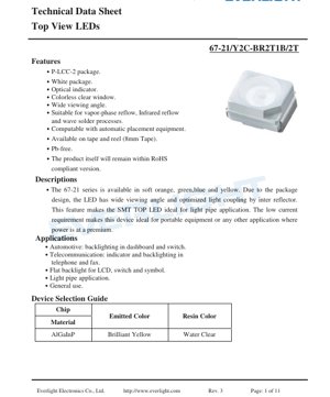
1. مرور کلی محصول سری 67-21 خانوادهای از LEDهای SMD نمای بالا است که برای کاربردهای نشانگر و نور پسزمینه طراحی شدهاند. این مدل خاص که با پسوند شماره قطعه نشاندهنده انتشار زرد درخشان است، برای ارائه عملکردی قابل اعتماد در یک بستهبندی فشرده و استاندارد صنعتی P-LCC-2 مهندسی شده است. قطعه دارای بدنه سفید با پنجره شفاف بیرنگ است که به زاویه دید گسترده آن کمک میکند و آن را به ویژه برای استفاده با لولههای نوری (لایت پایپ) مناسب میسازد تا نور را به مناطق خاصی در پنل یا نمایشگر هدایت کند.
مزیت اصلی این LED در طراحی اپتیکی بهینه آن نهفته است. یک بازتابنده داخلی در بستهبندی، کارایی جفتشدن نور را افزایش میدهد و خروجی روشن و یکنواختی را تضمین میکند. علاوه بر این، نیاز به جریان مستقیم پایین آن، آن را به انتخابی ایدهآل برای تجهیزات قابل حمل با باتری یا حساس به توان تبدیل میکند، جایی که به حداقل رساندن مصرف انرژی حیاتی است. این قطعه کاملاً با الزامات تولید بدون سرب (Pb-free) مطابقت دارد و از دستورالعملهای RoHS پیروی میکند و آن را برای بازارهای جهانی با مقررات سخت زیستمحیطی مناسب میسازد.
2. بررسی عمیق پارامترهای فنی
2.1 محدودههای حداکثر مطلق این مقادیر محدودیتهایی را تعریف میکنند که فراتر از آن ممکن است آسیب دائمی به قطعه وارد شود. این مقادیر برای عملکرد عادی در نظر گرفته نشدهاند.
ولتاژ معکوس (V_R): 5 ولت. تجاوز از این ولتاژ در بایاس معکوس میتواند باعث شکست پیوند شود.
جریان مستقیم پیوسته (I_F): 50 میلیآمپر. حداکثر جریان DC که میتوان به طور پیوسته اعمال کرد.
- جریان مستقیم پیک (I_FP): 120 میلیآمپر. این حداکثر جریان پالسی مجاز است که تحت چرخه کاری 1/10 در فرکانس 1 کیلوهرتز مشخص شده است. این پارامتر برای کاربردهای شامل فلاشهای کوتاه و با شدت بالا حیاتی است.Rاتلاف توان (P_D): 100 میلیوات. این حداکثر توانی است که بستهبندی میتواند به صورت گرما دفع کند و از ضرب ولتاژ مستقیم (V_F) در جریان مستقیم (I_F) محاسبه میشود.تخلیه الکترواستاتیک (ESD) مدل بدن انسان (HBM): 2000 ولت. این رتبهبندی حساسیت LED به الکتریسیته ساکن را نشان میدهد. رعایت رویههای صحیح کنترل ESD در حین مونتاژ ضروری است.
- دمای عملیاتی (T_opr): 40- درجه سانتیگراد تا 85+ درجه سانتیگراد. محدوده دمای محیطی که در آن قطعه تضمین میشود تا مشخصات الکترواپتیکی خود را برآورده کند.Fدمای نگهداری (T_stg): 40- درجه سانتیگراد تا 90+ درجه سانتیگراد.دمای لحیمکاری: قطعه میتواند لحیمکاری رفلو با دمای پیک 260 درجه سانتیگراد را تا 10 ثانیه تحمل کند، یا لحیمکاری دستی در دمای 350 درجه سانتیگراد را تا 3 ثانیه.
- 2.2 مشخصات الکترواپتیکی این پارامترها در شرایط آزمایش استاندارد دمای محیط 25 درجه سانتیگراد و جریان مستقیم (I_F) 20 میلیآمپر اندازهگیری میشوند که نقطه کار معمول است.FPشدت نور (I_V): از حداقل 140 میلیکاندلا تا حداکثر 360 میلیکاندلا متغیر است. مقدار معمول در این محدوده قرار دارد و روشنایی خاص توسط فرآیند دستهبندی تعیین میشود.زاویه دید (2θ_1/2): 120 درجه (معمول). این زاویه کاملای است که در آن شدت نور به نصف مقدار حداکثر خود (روی محور) کاهش مییابد. زاویه گسترده یک ویژگی کلیدی برای کاربردهایی است که نیاز به قابلیت مشاهده از موقعیتهای خارج از محور دارند.
- طول موج پیک (λ_P): 591 نانومتر (معمول). طول موجی که در آن توزیع توان طیفی در حداکثر خود است.dطول موج غالب (λ_D): 588.5 نانومتر تا 594.5 نانومتر. این درک تکطولموجی چشم انسان از رنگ LED است و پارامتر اصلی برای دستهبندی رنگ محسوب میشود.پهنای باند طیفی (Δλ): 15 نانومتر (معمول). عرض طیف منتشر شده در نصف حداکثر توان آن (عرض کامل در نصف بیشینه - FWHM).Fولتاژ مستقیم (V_F): 1.75 ولت تا 2.35 ولت در I_F=20mA. افت ولتاژ در دو سر LED هنگامی که در حال هدایت است. این محدوده برای طراحی مدار محدودکننده جریان مهم است.Fجریان معکوس (I_R): حداکثر 10 میکروآمپر در V_R=5V. یک جریان نشتی بسیار پایین هنگامی که LED در بایاس معکوس قرار دارد.
- 3. توضیح سیستم دستهبندی (بینینگ) برای اطمینان از ثبات رنگ و روشنایی در تولید، LEDها بر اساس پارامترهای کلیدی در دستهها (بین) مرتب میشوند. سری 67-21 از یک سیستم دستهبندی سهبعدی استفاده میکند.3.1 دستهبندی طول موج غالب (HUE) این پارامتر سایه دقیق رنگ زرد را تعیین میکند. دستهها با گروه "B" و کدهای D4 و D5 برچسبگذاری شدهاند. دسته D4: طول موج غالب از 588.5 نانومتر تا 591.5 نانومتر. دسته D5: طول موج غالب از 591.5 نانومتر تا 594.5 نانومتر. یک تلرانس ±1 نانومتر به این محدودههای دسته اعمال میشود.
- 3.2 دستهبندی شدت نور (CAT) این پارامتر سطح روشنایی را تعیین میکند. دستهها با کدهای R2، S1، S2 و T1 تعریف شدهاند. دسته R2: 140 میلیکاندلا تا 180 میلیکاندلا. دسته S1: 180 میلیکاندلا تا 225 میلیکاندلا. دسته S2: 225 میلیکاندلا تا 285 میلیکاندلا. دسته T1: 285 میلیکاندلا تا 360 میلیکاندلا. یک تلرانس ±11% به شدت نور اعمال میشود.3.3 دستهبندی ولتاژ مستقیم (REF) این پارامتر LEDهایی با مشخصات الکتریکی مشابه را گروهبندی میکند که میتواند طراحی منبع تغذیه را ساده کند. دستهها با گروه "B" و کدهای 0، 1 و 2 برچسبگذاری شدهاند. دسته 0: از 1.75 ولت تا 1.95 ولت. دسته 1: از 1.95 ولت تا 2.15 ولت. دسته 2: از 2.15 ولت تا 2.35 ولت. یک تلرانس ±0.1 ولت به ولتاژ مستقیم اعمال میشود.4. تحلیل منحنیهای عملکرد دیتاشیت چندین منحنی مشخصه ارائه میدهد که برای درک رفتار LED تحت شرایط مختلف ضروری هستند.4.1 شدت نور نسبی در مقابل دمای محیط این منحنی نشان میدهد که خروجی نور LED با افزایش دمای محیط کاهش مییابد. در حداکثر دمای عملیاتی 85+ درجه سانتیگراد، شدت نور نسبی به طور قابل توجهی کمتر از دمای 25 درجه سانتیگراد است. این کاهش حرارتی باید در طراحیهایی که دمای محیط بالا انتظار میرود، مانند کاربردهای خودرو یا نزدیک اجزای تولیدکننده گرما، در نظر گرفته شود.
- 4.2 جریان مستقیم در مقابل ولتاژ مستقیم (منحنی I-V) منحنی I-V غیرخطی است که مشخصه یک دیود است. این منحنی رابطه بین جریان عبوری از LED و ولتاژ دو سر آن را نشان میدهد. منحنی برای انتخاب مقاومت محدودکننده جریان مناسب یا طراحی درایور جریان ثابت ضروری است. "زانو" منحنی، جایی که هدایت شروع میشود، برای این قطعه حدود 1.6 ولت تا 1.8 ولت است.4.3 شدت نور نسبی در مقابل جریان مستقیم این منحنی نشان میدهد که خروجی نور با جریان مستقیم افزایش مییابد، اما نه به صورت کاملاً خطی، به ویژه در جریانهای بالاتر. همچنین اهمیت عملکرد در محدودههای حداکثر مطلق را برجسته میکند؛ راهاندازی LED فراتر از جریان مشخص شده آن، افزایش متناسبی در روشنایی ایجاد نمیکند و گرمای بیش از حد تولید میکند که عمر مفید را کاهش میدهد.4.4 توزیع طیف نمودار طیفی یک قله غالب واحد را نشان میدهد که حول 591 نانومتر متمرکز است و رنگ زرد درخشان را تأیید میکند. پهنای باند باریک نشاندهنده خلوص رنگ خوب است. انتشار حداقلی در مناطق قرمز عمیق یا سبز وجود دارد که برای یک نشانگر زرد خالص مطلوب است.4.5 الگوی تابش نمودار قطبی به صورت بصری زاویه دید گسترده 120 درجه را تأیید میکند. توزیع شدت تقریباً لامبرتی (شبیه کسینوس) است، به این معنی که در هنگام مشاهده مستقیم درخشانترین است و به تدریج به سمت لبههای مخروط دید کاهش مییابد.
- 5. اطلاعات مکانیکی و بستهبندی5.1 ابعاد بستهبندی LED در یک بستهبندی P-LCC-2 (حامل تراشه سربی پلاستیکی) قرار دارد. ابعاد کلیدی شامل اندازه بدنه تقریباً 3.2 میلیمتر در 2.8 میلیمتر، با ارتفاع 1.9 میلیمتر است. بستهبندی دارای دو پایه بالمرغی برای نصب سطحی است. کاتد معمولاً توسط یک شکاف یا علامت سبز روی بستهبندی شناسایی میشود. نقشههای ابعادی دقیق با تلرانس ±0.1 میلیمتر در دیتاشیت برای طراحی جای پای PCB ارائه شده است.
5.2 شناسایی قطبیت قطبیت صحیح برای عملکرد حیاتی است. بستهبندی شامل نشانگرهای بصری است. پایه کاتد (-) اغلب با یک نقطه سبز یا یک شکاف کوچک روی بدنه بستهبندی نشان داده میشود. طراحان باید نقشه بستهبندی را با جای پای PCB توصیه شده مقایسه کنند تا اطمینان حاصل شود که پدهای آند و کاتد به درستی جهتگیری شدهاند.
6. دستورالعملهای لحیمکاری و مونتاژF6.1 پارامترهای لحیمکاری رفلو قطعه با فرآیندهای رفلو فاز بخار و مادون قرمز سازگار است. پروفایل توصیه شده دارای دمای پیک 260 درجه سانتیگراد است که نباید بیش از 10 ثانیه تجاوز کند. این یک پروفایل استاندارد برای خمیرهای لحیم بدون سرب (SnAgCu) است. نرخهای پیشگرمایش و خنکسازی باید کنترل شوند تا تنش حرارتی روی بستهبندی به حداقل برسد.
- 6.2 لحیمکاری دستی در صورت نیاز به لحیمکاری دستی، دمای نوک هویه نباید از 350 درجه سانتیگراد تجاوز کند و زمان تماس با هر پایه باید حداکثر به 3 ثانیه محدود شود. میتوان از یک سینک حرارتی روی پایه بین اتصال و بدنه بستهبندی استفاده کرد تا تراشه LED از گرمای بیش از حد محافظت شود.V6.3 شرایط نگهداری LEDها در کیسههای مهر و موم شده مقاوم در برابر رطوبت با ماده خشککن بستهبندی میشوند تا از جذب رطوبت جلوگیری شود که میتواند باعث "ترکیدن" (ترک خوردن بستهبندی) در حین رفلو شود. پس از باز شدن کیسه مهر و موم شده، قطعات باید در یک بازه زمانی مشخص (معمولاً 168 ساعت در شرایط کارخانه) استفاده شوند یا مطابق با مشخصات سطح حساسیت به رطوبت (MSL) که باید از سازنده دریافت شود، مجدداً خشک شوند.7. اطلاعات بستهبندی و سفارش
- 7.1 مشخصات نوار و قرقره قطعات روی نوار حامل برجسته به عرض 8 میلیمتر عرضه میشوند. هر قرقره حاوی 2000 قطعه است. ابعاد دقیق جیبهای نوار حامل و قرقره ارائه شده است تا سازگاری با تجهیزات اتوماتیک برداشت و قراردهی (پیک اند پلیس) تضمین شود.7.2 توضیح برچسب و شماره قطعه برچسب قرقره حاوی اطلاعات حیاتی برای ردیابی و مونتاژ صحیح است: CAT: کد دسته شدت نور (مثلاً S1، T1). HUE: کد دسته طول موج غالب (مثلاً D4، D5). REF: کد دسته ولتاژ مستقیم (مثلاً 0، 1، 2). شماره قطعه (PN)، شماره قطعه مشتری (CPN)، تعداد (QTY) و شماره سری ساخت برای ردیابی. شماره قطعه کامل (مثلاً 67-21/Y2C-BR2T1B/2T) سری، رنگ، دسته روشنایی و سایر ویژگیهای خاص سیستم سازنده را کدگذاری میکند.8. پیشنهادات کاربردی8.1 سناریوهای کاربردی متداول الکترونیک خودرو: نور پسزمینه برای ابزارهای داشبورد، کلیدها و پنلهای کنترل. زاویه دید گسترده و قابلیت اطمینان در محدوده دمایی وسیع، آن را برای این محیط سخت مناسب میسازد. تجهیزات مخابراتی: نشانگرهای وضعیت و نور پسزمینه صفحه کلید در تلفنها، فکسها و سختافزارهای شبکه. الکترونیک مصرفی: نشانگرهای برق، روشنایی دکمهها و چراغهای وضعیت در دستگاههای قابل حمل، لوازم خانگی و تجهیزات صوتی/تصویری. نشانگرهای پنل عمومی: هر کاربرد که نیاز به یک نشانگر وضعیت روشن، قابل اعتماد و فشرده دارد.
- 8.2 ملاحظات طراحی محدود کردن جریان: همیشه از یک مقاومت سری یا درایور جریان ثابت برای تنظیم جریان مستقیم استفاده کنید. مقدار مقاومت را با استفاده از R = (V_منبع - V_F) / I_F محاسبه کنید. از حداکثر V_F از دیتاشیت استفاده کنید تا اطمینان حاصل شود که جریان حتی با تغییرات قطعه به قطعه از حد مجاز تجاوز نمیکند. مدیریت حرارتی: در حالی که اتلاف توان پایین است، اطمینان حاصل کنید که مساحت کافی مس PCB یا وایاهای حرارتی زیر پد حرارتی (در صورت وجود) برای هدایت گرما وجود دارد، به ویژه در کاربردهای با دمای محیط بالا یا هنگام راهاندازی با جریانهای بالاتر. جفتشدن لوله نوری: برای کاربردهای لوله نوری، LED را تا حد امکان نزدیک به ورودی لوله نوری قرار دهید. زاویه دید گسترده به جذب نور بیشتر کمک میکند، اما همترازی دقیق همچنان کلید به حداکثر رساندن کارایی و دستیابی به روشنایی یکنواخت در خروجی است. محافظت ESD: در صورت دسترسی مستقیم کاربران به LED (مثلاً روی پنل جلویی)، محافظت ESD را روی خطوط ورودی پیادهسازی کنید. در حین جابجایی و مونتاژ، اقدامات احتیاطی استاندارد ESD را رعایت کنید.p9. مقایسه و تمایز فنی سری 67-21 خود را در بازار LEDهای نشانگر SMD از طریق چندین ویژگی کلیدی متمایز میکند. در مقایسه با بستهبندیهای قدیمی و کوچکتر (مانند 0402 یا 0603)، به دلیل تراشه بزرگتر و بازتابنده داخلی بهینهشده، خروجی نور به مراتب بالاتر و زاویه دید بسیار گستردهتری ارائه میدهد. در مقابل سایر بستهبندیهای P-LCC-2، ترکیب خاص آن از رنگ زرد درخشان (بر اساس ماده AlGaInP برای بازدهی بالا)، ساختار دستهبندی مشخص برای ثبات، و مشخصات قوی برای لحیمکاری رفلو، آن را به انتخابی قابل اعتماد برای تولید انبوه تبدیل میکند. نیاز به ولتاژ مستقیم پایین آن نیز یک مزیت متمایز در طراحیهای با باتری است، زیرا فضای ولتاژ مورد نیاز از منبع تغذیه را کاهش میدهد و به طور بالقوه عمر باتری را افزایش میدهد.10. پرسشهای متداول (بر اساس پارامترهای فنی)
- 10.1 تفاوت بین طول موج پیک و طول موج غالب چیست؟ طول موج پیک (λ_P) طول موج فیزیکی است که LED بیشترین توان نوری را در آن منتشر میکند. طول موج غالب (λ_D) یک مقدار محاسبهشده است که نشاندهنده طول موج تکرنگ نور است که برای چشم انسان همان رنگ را دارد. طول موج غالب برای درک رنگ مرتبطتر است و برای دستهبندی استفاده میشود.d10.2 آیا میتوانم این LED را با منبع تغذیه 3.3V و بدون مقاومت راهاندازی کنم؟ خیر، این توصیه نمیشود و به احتمال زیاد LED را از بین میبرد. یک LED یک قطعه جریانمحور است. بدون یک مکانیسم محدودکننده جریان (یک مقاومت یا درایور فعال)، اتصال مستقیم آن به یک منبع ولتاژ مانند 3.3V باعث جریان بیش از حد میشود که به مراتب از رتبه حداکثر 50 میلیآمپر فراتر میرود و منجر به گرمای بیش از حد فوری و خرابی میشود.10.3 چرا شدت نور در دمای بالا کاهش مییابد؟ این یک ویژگی اساسی منابع نور نیمههادی است. با افزایش دما، فرآیندهای بازترکیب غیرتابشی درون ماده نیمههادی غالبتر میشوند و بازده کوانتومی داخلی (تعداد فوتونهای تولید شده به ازای هر الکترون) را کاهش میدهند. این امر منجر به خروجی نور کمتر برای همان جریان راهاندازی میشود.
- 10.4 چگونه دسته مناسب را برای کاربرد خود انتخاب کنم؟ انتخاب به نیازهای شما بستگی دارد: برای ثبات رنگ در بین چندین LED در یک محصول، یک دسته HUE محدود را مشخص کنید (مثلاً فقط D4). برای ثبات روشنایی، یک دسته CAT محدود را مشخص کنید (مثلاً فقط T1 برای بالاترین روشنایی). برای سادهسازی طراحی منبع تغذیه در سیستمهای ولتاژ ثابت، مشخص کردن یک دسته REF محدود (مثلاً فقط دسته 1) جریان کشی قابل پیشبینیتری را تضمین میکند. برای بررسی موجودی و پیامدهای هزینه ترکیبهای دسته خاص، با تأمینکننده قطعه مشورت کنید.11. مطالعه موردی طراحی عملی سناریو: طراحی یک نشانگر وضعیت برای یک دستگاه پزشکی قابل حمل. نشانگر باید در شرایط نوری مختلف به وضوح قابل مشاهده باشد، حداقل توان را مصرف کند تا عمر باتری به حداکثر برسد و تمیز کردن گاهبهگاه با مواد ضدعفونیکننده را تحمل کند. پیادهسازی: LED زرد درخشان سری 67-21 انتخاب میشود. یک لوله نوری طراحی میشود تا نور را از LED که روی PCB اصلی نصب شده است، به یک پنجره کوچک روی پنل جلویی مهر و موم شده دستگاه هدایت کند. این کار LED را از تماس فیزیکی و مایعات محافظت میکند. مدار راهاندازی از یک پین GPIO میکروکنترلر، یک مقاومت محدودکننده جریان 100 اهم متصل به ریل 3.3 ولت استفاده میکند که منجر به جریان مستقیم تقریبی (3.3V - 2.0V)/100Ω = 13mA میشود که به خوبی در محدوده عملیاتی ایمن قرار دارد. این امر روشنایی کافی را فراهم میکند و در عین حال مصرف توان را به حداقل میرساند. زاویه دید گسترده LED اطمینان میدهد که لوله نوری به طور کارآمد پر میشود و درخششی یکنواخت در پنل ایجاد میکند.
- 12. معرفی اصل عملکرد این LED بر اساس یک تراشه نیمههادی فسفید آلومینیوم گالیم ایندیم (AlGaInP) ساخته شده است. هنگامی که یک ولتاژ مستقیم بیش از آستانه روشن شدن دیود اعمال میشود، الکترونها از ناحیه نوع n و حفرهها از ناحیه نوع p به ناحیه فعال تزریق میشوند. این حاملهای بار بازترکیب میشوند و انرژی را به شکل فوتون (نور) آزاد میکنند. ترکیب خاص آلیاژ AlGaInP انرژی شکاف باند نیمههادی را تعیین میکند که مستقیماً طول موج (رنگ) نور منتشر شده را دیکته میکند. برای زرد درخشان، شکاف باند مربوط به فوتونهایی با انرژی حدود 2.1 الکترونولت (طول موج ~590 نانومتر) است. نور تولید شده سپس از بالای تراشه استخراج میشود و توسط بازتابنده داخلی و لنز اپوکسی شفاف بستهبندی P-LCC-2 شکل داده و هدایت میشود.F13. روندها و تحولات فناوری روند کلی در LEDهای نشانگر SMD مانند سری 67-21 به سمت بازدهی بالاتر (خروجی نور بیشتر به ازای هر میلیآمپر جریان) است که امکان نشانگرهای روشنتر یا مصرف توان پایینتر را فراهم میکند. همچنین تلاشی برای بهبود ثبات رنگ و دستهبندی دقیقتر از ویفر به ویفر وجود دارد. فناوری بستهبندی همچنان در حال تکامل است و تحولات آینده بالقوه شامل پروفایلهای حتی نازکتر برای کاربردهای با محدودیت فضا و مواد با رسانایی حرارتی بالاتر برای مدیریت بهتر گرما در جریانهای راهاندازی بالاتر است. علاوه بر این، ادغام با کنترل رویبرد، مانند داشتن یک IC کوچک برای تنظیم نور PWM یا توالی رنگ درون همان بستهبندی، روندی رو به رشد در بازار گستردهتر LED است، اگرچه ممکن است برای LEDهای چندرنگ یا آدرسپذیر مرتبطتر باشد تا نشانگرهای تکرنگ استاندارد..75 V to 2.35 V at IF=20mA. The voltage drop across the LED when it is conducting. This range is important for designing the current-limiting circuitry.
- Reverse Current (IR):Maximum 10 μA at VR=5V. A very low leakage current when the LED is reverse-biased.
. Binning System Explanation
To ensure color and brightness consistency in production, LEDs are sorted into bins based on key parameters. The 67-21 series uses a three-dimensional binning system.
.1 Dominant Wavelength Binning (HUE)
This determines the precise shade of yellow. The bins are labeled with group "B" and codes D4 and D5.
- Bin D4:Dominant Wavelength from 588.5 nm to 591.5 nm.
- Bin D5:Dominant Wavelength from 591.5 nm to 594.5 nm.
.2 Luminous Intensity Binning (CAT)
This determines the brightness level. The bins are defined by codes R2, S1, S2, and T1.
- Bin R2: mcd to 180 mcd.
- Bin S1: mcd to 225 mcd.
- Bin S2: mcd to 285 mcd.
- Bin T1: mcd to 360 mcd.
.3 Forward Voltage Binning (REF)
This groups LEDs with similar electrical characteristics, which can simplify power supply design. The bins are labeled with group "B" and codes 0, 1, and 2.
- Bin 0: VFfrom 1.75 V to 1.95 V.
- Bin 1: VFfrom 1.95 V to 2.15 V.
- Bin 2: VFfrom 2.15 V to 2.35 V.
. Performance Curve Analysis
The datasheet provides several characteristic curves that are essential for understanding the LED's behavior under different conditions.
.1 Relative Luminous Intensity vs. Ambient Temperature
This curve shows that the light output of the LED decreases as the ambient temperature increases. At the maximum operating temperature of +85°C, the relative luminous intensity is significantly lower than at 25°C. This thermal derating must be accounted for in designs where high ambient temperatures are expected, such as in automotive applications or near heat-generating components.
.2 Forward Current vs. Forward Voltage (I-V Curve)
The I-V curve is non-linear, typical of a diode. It shows the relationship between the current flowing through the LED and the voltage across it. The curve is essential for selecting an appropriate current-limiting resistor or designing a constant-current driver. The "knee" of the curve, where conduction begins, is around 1.6V to 1.8V for this device.
.3 Relative Luminous Intensity vs. Forward Current
This curve demonstrates that light output increases with forward current, but not in a perfectly linear fashion, especially at higher currents. It also highlights the importance of operating within the Absolute Maximum Ratings; driving the LED beyond its specified current will not yield proportional increases in brightness and will generate excessive heat, reducing lifespan.
.4 Spectrum Distribution
The spectral graph shows a single, dominant peak centered around 591 nm, confirming the brilliant yellow color. The narrow bandwidth indicates good color purity. There is minimal emission in the deep red or green regions, which is desirable for a pure yellow indicator.
.5 Radiation Pattern
The polar diagram visually confirms the wide 120° viewing angle. The intensity distribution is roughly Lambertian (cosine-like), meaning it is brightest when viewed head-on and gradually decreases towards the edges of the viewing cone.
. Mechanical and Packaging Information
.1 Package Dimensions
The LED is housed in a P-LCC-2 (Plastic Leaded Chip Carrier) package. Key dimensions include a body size of approximately 3.2mm x 2.8mm, with a height of 1.9mm. The package features two gull-wing leads for surface mounting. The cathode is typically identified by a notch or a green marking on the package. Detailed dimensional drawings with tolerances of ±0.1mm are provided in the datasheet for PCB footprint design.
.2 Polarity Identification
Correct polarity is critical for operation. The package incorporates visual markers. The cathode (-) lead is often indicated by a green dot or a small notch on the package body. Designers must cross-reference the package drawing with the recommended PCB footprint to ensure the anode and cathode pads are correctly oriented.
. Soldering and Assembly Guidelines
.1 Reflow Soldering Parameters
The device is compatible with vapor-phase and infrared reflow processes. The recommended profile has a peak temperature of 260°C, which should not be exceeded for more than 10 seconds. This is a standard profile for lead-free (SnAgCu) solder pastes. Preheating and cooling rates should be controlled to minimize thermal stress on the package.
.2 Hand Soldering
If hand soldering is necessary, the iron tip temperature should not exceed 350°C, and contact time with each lead should be limited to a maximum of 3 seconds. A heat sink may be used on the lead between the joint and the package body to protect the LED die from excessive heat.
.3 Storage Conditions
The LEDs are packaged in moisture-resistant barrier bags with desiccant to prevent moisture absorption, which can cause "popcorning" (package cracking) during reflow. Once the sealed bag is opened, the components should be used within a specified time frame (typically 168 hours at factory conditions) or rebaked according to the moisture sensitivity level (MSL) specification, which should be obtained from the manufacturer.
. Packaging and Ordering Information
.1 Tape and Reel Specifications
The components are supplied on 8mm wide embossed carrier tape. Each reel contains 2000 pieces. Detailed dimensions for the carrier tape pockets and the reel are provided to ensure compatibility with automated pick-and-place equipment.
.2 Label Explanation and Part Numbering
The reel label contains critical information for traceability and correct assembly:
- CAT:The Luminous Intensity bin code (e.g., S1, T1).
- HUE:The Dominant Wavelength bin code (e.g., D4, D5).
- REF:The Forward Voltage bin code (e.g., 0, 1, 2).
- Part Number (PN), Customer Part Number (CPN), Quantity (QTY), and Lot Number for tracking.
. Application Suggestions
.1 Typical Application Scenarios
- Automotive Electronics:Backlighting for dashboard instruments, switches, and control panels. The wide viewing angle and reliability across a wide temperature range make it suitable for this demanding environment.
- Telecommunication Equipment:Status indicators and keypad backlighting in phones, fax machines, and networking hardware.
- Consumer Electronics:Power indicators, button illumination, and status lights in portable devices, home appliances, and audio/video equipment.
- General Panel Indicators:Any application requiring a bright, reliable, and compact status indicator.
.2 Design Considerations
- Current Limiting:Always use a series resistor or constant-current driver to set the forward current. Calculate the resistor value using R = (Vsupply- VF) / IF. Use the maximum VFfrom the datasheet to ensure the current does not exceed the limit even with part-to-part variation.
- Thermal Management:While the power dissipation is low, ensure adequate PCB copper area or thermal vias under the thermal pad (if present) to conduct heat away, especially in high ambient temperature applications or when driving at higher currents.
- Light Pipe Coupling:For light pipe applications, position the LED as close as possible to the entrance of the light pipe. The wide viewing angle helps capture more light, but precise alignment is still key to maximizing efficiency and achieving uniform illumination at the output.
- ESD Protection:Implement ESD protection on input lines if the LED is directly accessible to users (e.g., on a front panel). During handling and assembly, follow standard ESD precautions.
. Technical Comparison and Differentiation
The 67-21 series differentiates itself in the market of SMD indicator LEDs through several key features. Compared to older, smaller packages (like 0402 or 0603), it offers significantly higher light output and a much wider viewing angle due to its larger die and optimized internal reflector. Against other P-LCC-2 packages, its specific combination of a brilliant yellow color (based on AlGaInP material for high efficiency), well-defined binning structure for consistency, and robust specifications for reflow soldering make it a reliable choice for volume production. Its low forward voltage requirement is also a distinct advantage in battery-powered designs, as it reduces the voltage headroom needed from the power source, potentially extending battery life.
. Frequently Asked Questions (Based on Technical Parameters)
.1 What is the difference between Peak Wavelength and Dominant Wavelength?
Peak Wavelength (λp) is the physical wavelength where the LED emits the most optical power. Dominant Wavelength (λd) is a calculated value that represents the single wavelength of monochromatic light that would appear to have the same color to the human eye. Dominant wavelength is more relevant for color perception and is used for binning.
.2 Can I drive this LED with a 3.3V supply without a resistor?
No, this is not recommended and is likely to destroy the LED.An LED is a current-driven device. Without a current-limiting mechanism (a resistor or active driver), connecting it directly to a voltage source like 3.3V will cause excessive current to flow, far exceeding the 50mA maximum rating, leading to immediate overheating and failure.
.3 Why does the luminous intensity decrease at high temperature?
This is a fundamental characteristic of semiconductor light sources. As temperature increases, non-radiative recombination processes within the semiconductor material become more dominant, reducing the internal quantum efficiency (the number of photons generated per electron). This results in lower light output for the same drive current.
.4 How do I select the right bin for my application?
Selection depends on your requirements:
- For color consistencyacross multiple LEDs in a product, specify a tight HUE bin (e.g., only D4).
- For brightness consistency, specify a tight CAT bin (e.g., only T1 for highest brightness).
- For simplified power supply designin constant-voltage systems, specifying a tight REF bin (e.g., only Bin 1) ensures more predictable current draw.
. Practical Design Case Study
Scenario:Designing a status indicator for a portable medical device. The indicator must be clearly visible in various lighting conditions, consume minimal power to maximize battery life, and withstand occasional cleaning with disinfectants.
Implementation:The 67-21 brilliant yellow LED is selected. A light pipe is designed to channel light from the LED, mounted on the main PCB, to a small window on the device's sealed front panel. This protects the LED from physical contact and liquids. The drive circuit uses a GPIO pin from a microcontroller, a 100Ω current-limiting resistor connected to a 3.3V rail, resulting in a forward current of approximately (3.3V - 2.0V)/100Ω = 13mA, well within the safe operating area. This provides ample brightness while minimizing power consumption. The wide viewing angle of the LED ensures the light pipe is efficiently filled, giving a uniform glow at the panel.
. Operating Principle Introduction
This LED is based on an Aluminum Gallium Indium Phosphide (AlGaInP) semiconductor chip. When a forward voltage exceeding the diode's turn-on threshold is applied, electrons are injected from the n-type region and holes from the p-type region into the active region. These charge carriers recombine, releasing energy in the form of photons (light). The specific composition of the AlGaInP alloy determines the bandgap energy of the semiconductor, which directly dictates the wavelength (color) of the emitted light. For brilliant yellow, the bandgap corresponds to photons with energy around 2.1 eV (wavelength ~590 nm). The generated light is then extracted through the top of the chip, shaped and directed by the internal reflector and the clear epoxy lens of the P-LCC-2 package.
. Technology Trends and Developments
The general trend in SMD indicator LEDs like the 67-21 series is towards higher efficiency (more light output per milliampere of current), which allows for either brighter indicators or lower power consumption. There is also a drive for improved color consistency and tighter binning from wafer to wafer. Packaging technology continues to evolve, with potential future developments including even thinner profiles for space-constrained applications and materials with higher thermal conductivity to better manage heat at higher drive currents. Furthermore, integration with onboard control, such as having a tiny IC for PWM dimming or color sequencing within the same package, is a growing trend in the broader LED market, though it may be more relevant for multi-color or addressable LEDs than for standard single-color indicators.
اصطلاحات مشخصات LED
توضیح کامل اصطلاحات فنی LED
عملکرد نوربرقی
| اصطلاح | واحد/نمایش | توضیح ساده | چرا مهم است |
|---|---|---|---|
| بازده نوری | لومن/وات | خروجی نور در هر وات برق، بالاتر به معنای صرفهجویی بیشتر انرژی است. | مستقیماً درجه بازده انرژی و هزینه برق را تعیین میکند. |
| شار نوری | لومن | کل نور ساطع شده از منبع، معمولاً "روشنی" نامیده میشود. | تعیین میکند که نور به اندازه کافی روشن است یا نه. |
| زاویه دید | درجه، مثل 120 درجه | زاویهای که شدت نور به نصف کاهش مییابد، عرض پرتو را تعیین میکند. | بر محدوده روشنایی و یکنواختی تأثیر میگذارد. |
| دمای رنگ | کلوین، مثل 2700K/6500K | گرمی/سردی نور، مقادیر پایین زرد/گرم، مقادیر بالا سفید/سرد. | جو روشنایی و سناریوهای مناسب را تعیین میکند. |
| شاخص نمود رنگ | بدون واحد، 100-0 | توانایی ارائه دقیق رنگهای جسم، Ra≥80 خوب است. | بر اصالت رنگ تأثیر میگذارد، در مکانهای پرتقاضا مانند مراکز خرید، موزهها استفاده میشود. |
| تلرانس رنگ | مراحل بیضی مکآدام، مثل "5 مرحله" | متریک سازگاری رنگ، مراحل کوچکتر به معنای رنگ سازگارتر است. | رنگ یکنواخت را در سراسر همان دسته LEDها تضمین میکند. |
| طول موج غالب | نانومتر، مثل 620 نانومتر (قرمز) | طول موج متناظر با رنگ LEDهای رنگی. | فام قرمز، زرد، سبز LEDهای تکرنگ را تعیین میکند. |
| توزیع طیفی | منحنی طول موج در مقابل شدت | توزیع شدت در طول موجها را نشان میدهد. | بر نمود رنگ و کیفیت رنگ تأثیر میگذارد. |
پارامترهای الکتریکی
| اصطلاح | نماد | توضیح ساده | ملاحظات طراحی |
|---|---|---|---|
| ولتاژ مستقیم | Vf | حداقل ولتاژ برای روشن کردن LED، مانند "آستانه شروع". | ولتاژ درایور باید ≥Vf باشد، ولتاژها برای LEDهای سری جمع میشوند. |
| جریان مستقیم | If | مقدار جریان برای عملکرد عادی LED. | معمولاً درایو جریان ثابت، جریان روشنایی و طول عمر را تعیین میکند. |
| حداکثر جریان پالس | Ifp | جریان اوج قابل تحمل برای دورههای کوتاه، برای تاریکی یا فلاش استفاده میشود. | عرض پالس و چرخه وظیفه باید به شدت کنترل شود تا از آسیب جلوگیری شود. |
| ولتاژ معکوس | Vr | حداکثر ولتاژ معکوسی که LED میتواند تحمل کند، فراتر از آن ممکن است باعث شکست شود. | مدار باید از اتصال معکوس یا جهش ولتاژ جلوگیری کند. |
| مقاومت حرارتی | Rth (°C/W) | مقاومت در برابر انتقال حرارت از تراشه به لحیم، پایینتر بهتر است. | مقاومت حرارتی بالا نیاز به اتلاف حرارت قویتر دارد. |
| مقاومت ESD | V (HBM)، مثل 1000V | توانایی مقاومت در برابر تخلیه الکترواستاتیک، بالاتر به معنای کمتر آسیبپذیر است. | اقدامات ضد استاتیک در تولید لازم است، به ویژه برای LEDهای حساس. |
مدیریت حرارتی و قابلیت اطمینان
| اصطلاح | متریک کلیدی | توضیح ساده | تأثیر |
|---|---|---|---|
| دمای اتصال | Tj (°C) | دمای عملیاتی واقعی داخل تراشه LED. | هر کاهش 10°C ممکن است طول عمر را دو برابر کند؛ خیلی زیاد باعث افت نور، تغییر رنگ میشود. |
| افت لومن | L70 / L80 (ساعت) | زمانی که روشنایی به 70% یا 80% مقدار اولیه کاهش یابد. | مستقیماً "عمر خدمت" LED را تعریف میکند. |
| نگهداری لومن | % (مثل 70%) | درصد روشنایی باقیمانده پس از زمان. | نشاندهنده حفظ روشنایی در طول استفاده بلندمدت است. |
| تغییر رنگ | Δu′v′ یا بیضی مکآدام | درجه تغییر رنگ در حین استفاده. | بر یکنواختی رنگ در صحنههای روشنایی تأثیر میگذارد. |
| پیری حرارتی | تخریب ماده | تخریب ناشی از دمای بالا در بلندمدت. | ممکن است باعث افت روشنایی، تغییر رنگ یا خرابی مدار باز شود. |
بسته بندی و مواد
| اصطلاح | انواع رایج | توضیح ساده | ویژگیها و کاربردها |
|---|---|---|---|
| نوع بستهبندی | EMC، PPA، سرامیک | ماده محفظه محافظ تراشه، ارائه رابط نوری/حرارتی. | EMC: مقاومت حرارتی خوب، هزینه کم؛ سرامیک: اتلاف حرارت بهتر، عمر طولانیتر. |
| ساختار تراشه | جلو، تراشه معکوس | چینش الکترود تراشه. | تراشه معکوس: اتلاف حرارت بهتر، کارایی بالاتر، برای توان بالا. |
| پوشش فسفر | YAG، سیلیکات، نیترید | تراشه آبی را میپوشاند، مقداری را به زرد/قرمز تبدیل میکند، به سفید مخلوط میکند. | فسفرهای مختلف بر کارایی، CCT و CRI تأثیر میگذارند. |
| عدسی/اپتیک | مسطح، میکروعدسی، TIR | ساختار نوری روی سطح که توزیع نور را کنترل میکند. | زاویه دید و منحنی توزیع نور را تعیین میکند. |
کنترل کیفیت و دسته بندی
| اصطلاح | محتوای دستهبندی | توضیح ساده | هدف |
|---|---|---|---|
| دسته لومن | کد مثل 2G، 2H | گروهبندی بر اساس روشنایی، هر گروه مقادیر حداقل/حداکثر لومن دارد. | روشنایی یکنواخت را در همان دسته تضمین میکند. |
| دسته ولتاژ | کد مثل 6W، 6X | گروهبندی بر اساس محدوده ولتاژ مستقیم. | تسهیل تطبیق درایور، بهبود بازده سیستم. |
| دسته رنگ | بیضی مکآدام 5 مرحلهای | گروهبندی بر اساس مختصات رنگ، اطمینان از محدوده باریک. | یکنواختی رنگ را تضمین میکند، از رنگ ناهموار در داخل وسایل جلوگیری میکند. |
| دسته CCT | 2700K، 3000K و غیره | گروهبندی بر اساس CCT، هر کدام محدوده مختصات مربوطه را دارد. | الزامات CCT صحنه مختلف را برآورده میکند. |
آزمون و گواهینامه
| اصطلاح | استاندارد/آزمون | توضیح ساده | اهمیت |
|---|---|---|---|
| LM-80 | آزمون نگهداری لومن | روشنایی بلندمدت در دمای ثابت، ثبت افت روشنایی. | برای تخمین عمر LED استفاده میشود (با TM-21). |
| TM-21 | استاندارد تخمین عمر | عمر را تحت شرایط واقعی بر اساس دادههای LM-80 تخمین میزند. | پیشبینی علمی عمر ارائه میدهد. |
| IESNA | انجمن مهندسی روشنایی | روشهای آزمون نوری، الکتریکی، حرارتی را پوشش میدهد. | پایه آزمون شناخته شده صنعت. |
| RoHS / REACH | گواهی محیط زیست | اطمینان از عدم وجود مواد مضر (سرب، جیوه). | شرط دسترسی به بازار در سطح بینالمللی. |
| ENERGY STAR / DLC | گواهی بازده انرژی | گواهی بازده انرژی و عملکرد برای محصولات روشنایی. | در خریدهای دولتی، برنامههای یارانه استفاده میشود، رقابتپذیری را افزایش میدهد. |