Table of Contents
- 1. Product Overview
- 2. Technical Parameter Deep-Dive
- 2.1 Absolute Maximum Ratings
- 2.2 Electro-Optical Characteristics
- 3. Binning System Explanation
- 3.1 Dominant Wavelength Binning (HUE)
- 3.2 Luminous Intensity Binning (CAT)
- 3.3 Forward Voltage Binning (REF)
- 4. Performance Curve Analysis
- 4.1 Relative Luminous Intensity vs. Ambient Temperature
- 4.2 Forward Current vs. Forward Voltage (I-V Curve)
- 4.3 Relative Luminous Intensity vs. Forward Current
- 4.4 Spectrum Distribution
- 4.5 Radiation Pattern
- 5. Mechanical and Packaging Information
- 5.1 Package Dimensions
- 5.2 Polarity Identification
- 6. Soldering and Assembly Guidelines
- 6.1 Reflow Soldering Parameters
- 6.2 Hand Soldering
- 6.3 Storage Conditions
- 7. Packaging and Ordering Information
- 7.1 Tape and Reel Specifications
- 7.2 Label Explanation and Part Numbering
- 8. Application Suggestions
- 8.1 Typical Application Scenarios
- 8.2 Design Considerations
- 9. Technical Comparison and Differentiation
- 10. Frequently Asked Questions (Based on Technical Parameters)
- 10.1 What is the difference between Peak Wavelength and Dominant Wavelength?
- 10.2 Can I drive this LED with a 3.3V supply without a resistor?
- 10.3 Why does the luminous intensity decrease at high temperature?
- 10.4 Ta yaya zan zaɓi bin da ya dace don aikina?
- 11. Nazarin Shari'ar Ƙirar Aiki
- 12. Operating Principle Introduction
- 13. Technology Trends and Developments
1. Product Overview
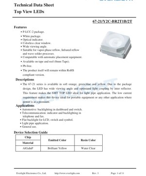
The 67-21 series represents a family of surface-mount Top View LEDs designed for indicator and backlighting applications. This specific variant, identified by the part number suffix indicating brilliant yellow emission, is engineered to provide reliable performance in a compact, industry-standard P-LCC-2 package. The device features a white package body with a colorless clear window, which contributes to its wide viewing angle and makes it particularly suitable for use with light pipes to guide illumination to specific areas on a panel or display.
The core advantage of this LED lies in its optimized optical design. An internal reflector within the package enhances light coupling efficiency, ensuring bright and uniform output. Furthermore, its low forward current requirement makes it an ideal choice for battery-powered or power-sensitive portable equipment, where minimizing energy consumption is critical. The device is fully compliant with lead-free (Pb-free) manufacturing requirements and adheres to RoHS directives, making it suitable for global markets with strict environmental regulations.
2. Technical Parameter Deep-Dive
2.1 Absolute Maximum Ratings
These ratings define the limits beyond which permanent damage to the device may occur. They are not intended for normal operation.
- Reverse Voltage (VR): 5 V. Exceeding this voltage in reverse bias can cause junction breakdown.
- Continuous Forward Current (IF): 50 mA. The maximum DC current that can be applied continuously.
- Peak Forward Current (IFP): 120 mA. This is the maximum allowable pulsed current, specified under a duty cycle of 1/10 at 1 kHz. It is crucial for applications involving brief, high-intensity flashes.
- Power Dissipation (Pd): 100 mW. This is the maximum power the package can dissipate as heat, calculated as Forward Voltage (VF) multiplied by Forward Current (IF).
- Electrostatic Discharge (ESD) Human Body Model (HBM): 2000 V. This rating indicates the LED's sensitivity to static electricity. Proper ESD handling procedures are necessary during assembly.
- Operating Temperature (Topr): -40°C to +85°C. The ambient temperature range over which the device is guaranteed to meet its electro-optical specifications.
- Storage Temperature (Tstg): -40°C to +90°C.
- Soldering Temperature: The device can withstand reflow soldering with a peak temperature of 260°C for up to 10 seconds, or hand soldering at 350°C for up to 3 seconds.
2.2 Electro-Optical Characteristics
These parameters are measured at a standard test condition of 25°C ambient temperature and a forward current (IF) of 20 mA, which is the typical operating point.
- Luminous Intensity (IV): Ranges from a minimum of 140 mcd to a maximum of 360 mcd. The typical value falls within this range, and specific brightness is determined by the binning process.
- Viewing Angle (2θ1/2): 120 degrees (typical). This is the full angle at which the luminous intensity drops to half of its maximum value (on-axis). The wide angle is a key feature for applications requiring visibility from off-axis positions.
- Peak Wavelength (λp): 591 nm (typical). The wavelength at which the spectral power distribution is at its maximum.
- Dominant Wavelength (λd): 588.5 nm to 594.5 nm. This is the single-wavelength perception of the LED's color by the human eye and is the primary parameter for color binning.
- Spectral Bandwidth (Δλ): 15 nm (typical). The width of the emitted spectrum at half its maximum power (Full Width at Half Maximum - FWHM).
- Forward Voltage (VF): 1.75 V to 2.35 V at IF=20mA. The voltage drop across the LED when it is conducting. This range is important for designing the current-limiting circuitry.
- Reverse Current (IR): Maximum 10 μA at VR=5V. A very low leakage current when the LED is reverse-biased.
3. Binning System Explanation
To ensure color and brightness consistency in production, LEDs are sorted into bins based on key parameters. The 67-21 series uses a three-dimensional binning system.
3.1 Dominant Wavelength Binning (HUE)
This determines the precise shade of yellow. The bins are labeled with group "B" and codes D4 and D5.
- Bin D4: Dominant Wavelength from 588.5 nm to 591.5 nm.
- Bin D5: Dominant Wavelength from 591.5 nm to 594.5 nm.
3.2 Luminous Intensity Binning (CAT)
This determines the brightness level. The bins are defined by codes R2, S1, S2, and T1.
- Bin R2: 140 mcd to 180 mcd.
- Bin S1: 180 mcd to 225 mcd.
- Bin S2: 225 mcd to 285 mcd.
- Bin T1: 285 mcd to 360 mcd.
3.3 Forward Voltage Binning (REF)
This groups LEDs with similar electrical characteristics, which can simplify power supply design. The bins are labeled with group "B" and codes 0, 1, and 2.
- Bin 0: VF from 1.75 V to 1.95 V.
- Bin 1: VF from 1.95 V to 2.15 V.
- Bin 2: VF from 2.15 V to 2.35 V.
4. Performance Curve Analysis
The datasheet provides several characteristic curves that are essential for understanding the LED's behavior under different conditions.
4.1 Relative Luminous Intensity vs. Ambient Temperature
This curve shows that the light output of the LED decreases as the ambient temperature increases. At the maximum operating temperature of +85°C, the relative luminous intensity is significantly lower than at 25°C. This thermal derating must be accounted for in designs where high ambient temperatures are expected, such as in automotive applications or near heat-generating components.
4.2 Forward Current vs. Forward Voltage (I-V Curve)
The I-V curve is non-linear, typical of a diode. It shows the relationship between the current flowing through the LED and the voltage across it. The curve is essential for selecting an appropriate current-limiting resistor or designing a constant-current driver. The "knee" of the curve, where conduction begins, is around 1.6V to 1.8V for this device.
4.3 Relative Luminous Intensity vs. Forward Current
This curve demonstrates that light output increases with forward current, but not in a perfectly linear fashion, especially at higher currents. It also highlights the importance of operating within the Absolute Maximum Ratings; driving the LED beyond its specified current will not yield proportional increases in brightness and will generate excessive heat, reducing lifespan.
4.4 Spectrum Distribution
The spectral graph shows a single, dominant peak centered around 591 nm, confirming the brilliant yellow color. The narrow bandwidth indicates good color purity. There is minimal emission in the deep red or green regions, which is desirable for a pure yellow indicator.
4.5 Radiation Pattern
The polar diagram visually confirms the wide 120° viewing angle. The intensity distribution is roughly Lambertian (cosine-like), meaning it is brightest when viewed head-on and gradually decreases towards the edges of the viewing cone.
5. Mechanical and Packaging Information
5.1 Package Dimensions
The LED is housed in a P-LCC-2 (Plastic Leaded Chip Carrier) package. Key dimensions include a body size of approximately 3.2mm x 2.8mm, with a height of 1.9mm. The package features two gull-wing leads for surface mounting. The cathode is typically identified by a notch or a green marking on the package. Detailed dimensional drawings with tolerances of ±0.1mm are provided in the datasheet for PCB footprint design.
5.2 Polarity Identification
Polarity e sahih bai da aiki. Kunshin ya ƙunshi alamomin gani. Ana nuna igiyar cathode (-) sau da yawa ta hanyar kore kore ko ƙaramin rami a jikin kunshin. Masu zane dole ne su yi kwatankwacin zanen kunshin tare da sawun PCB da aka ba da shawarar don tabbatar da cewa fakitin anode da cathode suna daidai.
6. Soldering and Assembly Guidelines
6.1 Reflow Soldering Parameters
The device is compatible with vapor-phase and infrared reflow processes. The recommended profile has a peak temperature of 260°C, which should not be exceeded for more than 10 seconds. This is a standard profile for lead-free (SnAgCu) solder pastes. Preheating and cooling rates should be controlled to minimize thermal stress on the package.
6.2 Hand Soldering
Idan an buƙatar yin sayar da hannu, zafin ƙarfen ba zai wuce 350°C ba, kuma lokacin tuntuɓar kowane jagora ya kamata ya iyakance zuwa mafi girman dakika 3. Ana iya amfani da ma'aunin zafi a kan jagora tsakanin haɗin gwiwa da jikin fakit ɗin don kare LED daga zafi mai yawa.
6.3 Storage Conditions
The LEDs are packaged in moisture-resistant barrier bags with desiccant to prevent moisture absorption, which can cause "popcorning" (package cracking) during reflow. Once the sealed bag is opened, the components should be used within a specified time frame (typically 168 hours at factory conditions) or rebaked according to the moisture sensitivity level (MSL) specification, which should be obtained from the manufacturer.
7. Packaging and Ordering Information
7.1 Tape and Reel Specifications
The components are supplied on 8mm wide embossed carrier tape. Each reel contains 2000 pieces. Detailed dimensions for the carrier tape pockets and the reel are provided to ensure compatibility with automated pick-and-place equipment.
7.2 Label Explanation and Part Numbering
The reel label contains critical information for traceability and correct assembly:
- CAT: The Luminous Intensity bin code (e.g., S1, T1).
- HUE: The Dominant Wavelength bin code (e.g., D4, D5).
- REF: The Forward Voltage bin code (e.g., 0, 1, 2).
- Part Number (PN), Customer Part Number (CPN), Quantity (QTY), and Lot Number for tracking.
8. Application Suggestions
8.1 Typical Application Scenarios
- Automotive Electronics: Backlighting for dashboard instruments, switches, and control panels. The wide viewing angle and reliability across a wide temperature range make it suitable for this demanding environment.
- Telecommunication Equipment: Status indicators and keypad backlighting in phones, fax machines, and networking hardware.
- Consumer Electronics: Power indicators, button illumination, and status lights in portable devices, home appliances, and audio/video equipment.
- General Panel Indicators: Any application requiring a bright, reliable, and compact status indicator.
8.2 Design Considerations
- Current Limiting: Always use a series resistor or constant-current driver to set the forward current. Calculate the resistor value using R = (Vsupply - VF) / IF. Use the maximum VF from the datasheet to ensure the current does not exceed the limit even with part-to-part variation.
- Thermal Management: While the power dissipation is low, ensure adequate PCB copper area or thermal vias under the thermal pad (if present) to conduct heat away, especially in high ambient temperature applications or when driving at higher currents.
- Light Pipe Coupling: For light pipe applications, position the LED as close as possible to the entrance of the light pipe. The wide viewing angle helps capture more light, but precise alignment is still key to maximizing efficiency and achieving uniform illumination at the output.
- ESD Protection: Implement ESD protection on input lines if the LED is directly accessible to users (e.g., on a front panel). During handling and assembly, follow standard ESD precautions.
9. Technical Comparison and Differentiation
The 67-21 series differentiates itself in the market of SMD indicator LEDs through several key features. Compared to older, smaller packages (like 0402 or 0603), it offers significantly higher light output and a much wider viewing angle due to its larger die and optimized internal reflector. Against other P-LCC-2 packages, its specific combination of a brilliant yellow color (based on AlGaInP material for high efficiency), well-defined binning structure for consistency, and robust specifications for reflow soldering make it a reliable choice for volume production. Its low forward voltage requirement is also a distinct advantage in battery-powered designs, as it reduces the voltage headroom needed from the power source, potentially extending battery life.
10. Frequently Asked Questions (Based on Technical Parameters)
10.1 What is the difference between Peak Wavelength and Dominant Wavelength?
Peak Wavelength (λp) is the physical wavelength where the LED emits the most optical power. Dominant Wavelength (λd) is a calculated value that represents the single wavelength of monochromatic light that would appear to have the same color to the human eye. Dominant wavelength is more relevant for color perception and is used for binning.
10.2 Can I drive this LED with a 3.3V supply without a resistor?
No, this is not recommended and is likely to destroy the LED. LED ni abin da ke tafiyar da halin yanzu. Ba tare da tsarin iyakancewar halin yanzu (resistor ko direba mai aiki) ba, haɗa shi kai tsaye zuwa tushen ƙarfin lantarki kamar 3.3V zai haifar da wuce gona da iri na halin yanzu, wanda ya wuce iyakar 50mA, wanda ke haifar da zafi da gazawar nan take.
10.3 Why does the luminous intensity decrease at high temperature?
Wannan shine ainihin halayen tushen haske na semiconductor. Yayin da zafin jiki ya karu, hanyoyin sake haɗuwa marasa haske a cikin kayan semiconductor sun zama mafi rinjaye, suna rage ingancin quantum na ciki (adadin photons da aka samar kowane electron). Wannan yana haifar da ƙananan fitar da haske don irin wannan halin yanzu na tuƙi.
10.4 Ta yaya zan zaɓi bin da ya dace don aikina?
Selection depends on your requirements:
- For color consistency Across multiple LEDs in a product, specify a tight HUE bin (e.g., only D4).
- For brightness consistency, specify a tight CAT bin (e.g., only T1 for highest brightness).
- For simplified power supply design in constant-voltage systems, specifying a tight REF bin (e.g., only Bin 1) ensures more predictable current draw.
11. Nazarin Shari'ar Ƙirar Aiki
Scenario: Designing a status indicator for a portable medical device. The indicator must be clearly visible in various lighting conditions, consume minimal power to maximize battery life, and withstand occasional cleaning with disinfectants.
Implementation: 67-21 brilliant yellow LED dinan. Light pipe dirancang untuk menyalurkan cahaya dari LED, yang dipasang di PCB utama, ke jendela kecil di panel depan perangkat yang tertutup rapat. Ini melindungi LED dari kontak fisik dan cairan. Rangkaian penggerak menggunakan pin GPIO dari mikrokontroler, resistor pembatas arus 100Ω yang terhubung ke rel 3.3V, menghasilkan arus maju sekitar (3.3V - 2.0V)/100Ω = 13mA, yang masih berada dalam area operasi aman. Ini memberikan kecerahan yang cukup sambil meminimalkan konsumsi daya. Sudut pandang LED yang lebar memastikan light pipe terisi secara efisien, memberikan cahaya seragam di panel.
12. Operating Principle Introduction
LED ini berbasis pada chip semikonduktor Aluminum Gallium Indium Phosphide (AlGaInP). Ketika tegangan maju yang melebihi ambang hidup dioda diterapkan, elektron disuntikkan dari daerah tipe-n dan lubang dari daerah tipe-p ke daerah aktif. Pembawa muatan ini bergabung kembali, melepaskan energi dalam bentuk foton (cahaya). Komposisi spesifik dari paduan AlGaInP menentukan energi celah pita semikonduktor, yang secara langsung menentukan panjang gelombang (warna) cahaya yang dipancarkan. Untuk kuning terang, celah pita sesuai dengan foton yang memiliki energi sekitar 2.1 eV (panjang gelombang ~590 nm). Cahaya yang dihasilkan kemudian diekstraksi melalui bagian atas chip, dibentuk dan diarahkan oleh reflektor internal dan lensa epoksi bening dari paket P-LCC-2.
13. Technology Trends and Developments
Babban yanayin gaba a cikin SMD nuna alamun LED kamar jerin 67-21 yana zuwa ga ingantaccen inganci (ƙarin fitowar haske a kowace milliampere na halin yanzu), wanda ke ba da damar ko dai masu nuna alama masu haske ko ƙarancin amfani da wutar lantarki. Hakanan akwai yunƙuri don ingantacciyar daidaiton launi da ƙaramin binning daga wafer zuwa wafer. Fasahar marufi tana ci gaba da haɓakawa, tare da yuwuwar ci gaba na gaba da suka haɗa da har ma da bayanan martaba mafi sirara don aikace-aikacen da ke da ƙarancin sarari da kayan aiki tare da mafi girman thermal conductivity don sarrafa zafi mafi kyau a manyan hanyoyin tuƙi. Bugu da ƙari, haɗin kai tare da sarrafa kan jirgi, kamar samun ƙaramin IC don PWM dimming ko jerin launi a cikin fakitin guda ɗaya, wani yanayi ne mai girma a cikin babbar kasuwar LED, kodayake yana iya zama mafi dacewa ga LED masu launi da yawa ko masu adireshi fiye da ma'auni na nuna alama mai launi ɗaya.
LED Specification Terminology
Complete explanation of LED technical terms
Photoelectric Performance
| Term | Unit/Representation | Simple Explanation | Why Important |
|---|---|---|---|
| Luminous Efficacy | lm/W (lumens per watt) | Light output per watt of electricity, higher means more energy efficient. | Directly determines energy efficiency grade and electricity cost. |
| Luminous Flux | lm (lumens) | Total light emitted by source, commonly called "brightness". | Determines if the light is bright enough. |
| Viewing Angle | ° (degrees), e.g., 120° | Angle where light intensity drops to half, determines beam width. | Affects illumination range and uniformity. |
| CCT (Color Temperature) | K (Kelvin), e.g., 2700K/6500K | Warmth/coolness of light, lower values yellowish/warm, higher whitish/cool. | Determines lighting atmosphere and suitable scenarios. |
| CRI / Ra | Unitless, 0–100 | Ability to render object colors accurately, Ra≥80 is good. | Affects color authenticity, used in high-demand places like malls, museums. |
| SDCM | MacAdam ellipse steps, e.g., "5-step" | Color consistency metric, smaller steps mean more consistent color. | Inahakikisha rangi sawa kwenye kundi moja la LED. |
| Dominant Wavelength | nm (nanometers), e.g., 620nm (red) | Wavelength corresponding to color of colored LEDs. | Determines hue of red, yellow, green monochrome LEDs. |
| Spectral Distribution | Wavelength vs intensity curve | Yana nuna yana nuna yana nuna yana nuna yana nuna. | Yana shafi launi da inganci. |
Electrical Parameters
| Term | Symbol | Simple Explanation | Design Considerations |
|---|---|---|---|
| Forward Voltage | Vf | Minimum voltage to turn on LED, like "starting threshold". | Driver voltage must be ≥Vf, voltages add up for series LEDs. |
| Forward Current | If | Current value for normal LED operation. | Usually constant current drive, current determines brightness & lifespan. |
| Max Pulse Current | Ifp | Peak current tolerable for short periods, used for dimming or flashing. | Pulse width & duty cycle must be strictly controlled to avoid damage. |
| Reverse Voltage | Vr | Max reverse voltage LED can withstand, beyond may cause breakdown. | Circuit must prevent reverse connection or voltage spikes. |
| Thermal Resistance | Rth (°C/W) | Resistance to heat transfer from chip to solder, lower is better. | High thermal resistance requires stronger heat dissipation. |
| ESD Immunity | V (HBM), e.g., 1000V | Ability to withstand electrostatic discharge, higher means less vulnerable. | Anti-static measures needed in production, especially for sensitive LEDs. |
Thermal Management & Reliability
| Term | Key Metric | Simple Explanation | Impact |
|---|---|---|---|
| Junction Temperature | Tj (°C) | Actual operating temperature inside LED chip. | Kila kupungua kwa 10°C kunaweza kuongeza maisha ya taa mara mbili; joto la juu sana husababisha kupungua kwa mwanga na mabadiliko ya rangi. |
| Kupungua kwa Lumen | L70 / L80 (saa) | Time for brightness to drop to 70% or 80% of initial. | Directly defines LED "service life". |
| Lumen Maintenance | % (e.g., 70%) | Percentage of brightness retained after time. | Indicates brightness retention over long-term use. |
| Color Shift | Δu′v′ or MacAdam ellipse | Degree of color change during use. | Affects color consistency in lighting scenes. |
| Thermal Aging | Material degradation | Deterioration due to long-term high temperature. | May cause brightness drop, color change, or open-circuit failure. |
Packaging & Materials
| Term | Common Types | Simple Explanation | Features & Applications |
|---|---|---|---|
| Package Type | EMC, PPA, Ceramic | Housing material protecting chip, providing optical/thermal interface. | EMC: good heat resistance, low cost; Ceramic: better heat dissipation, longer life. |
| Chip Structure | Front, Flip Chip | Chip electrode arrangement. | Flip chip: better heat dissipation, higher efficacy, for high-power. |
| Phosphor Coating | YAG, Silicate, Nitride | Covers blue chip, converts some to yellow/red, mixes to white. | Different phosphors affect efficacy, CCT, and CRI. |
| Lens/Optics | Flat, Microlens, TIR | Optical structure on surface controlling light distribution. | Determines viewing angle and light distribution curve. |
Quality Control & Binning
| Term | Binning Content | Simple Explanation | Purpose |
|---|---|---|---|
| Luminous Flux Bin | Code e.g., 2G, 2H | Grouped by brightness, each group has min/max lumen values. | Ensures uniform brightness in same batch. |
| Voltage Bin | Code e.g., 6W, 6X | Grouped by forward voltage range. | Facilitates driver matching, improves system efficiency. |
| Color Bin | 5-step MacAdam ellipse | Grouped by color coordinates, ensuring tight range. | Guarantees color consistency, avoids uneven color within fixture. |
| CCT Bin | 2700K, 3000K etc. | Grouped by CCT, each has corresponding coordinate range. | Meets different scene CCT requirements. |
Testing & Certification
| Term | Standard/Test | Simple Explanation | Significance |
|---|---|---|---|
| LM-80 | Lumen maintenance test | Long-term lighting at constant temperature, recording brightness decay. | Used to estimate LED life (with TM-21). |
| TM-21 | Standard ya kukadiria maisha | Inakadiria maisha chini ya hali halisi kulingana na data ya LM-80. | Provides scientific life prediction. |
| IESNA | Illuminating Engineering Society | Covers optical, electrical, thermal test methods. | Industry-recognized test basis. |
| RoHS / REACH | Environmental certification | Ensures no harmful substances (lead, mercury). | Market access requirement internationally. |
| ENERGY STAR / DLC | Energy efficiency certification | Energy efficiency and performance certification for lighting. | Used in government procurement, subsidy programs, enhances competitiveness. |