सामग्री
- 1. उत्पाद अवलोकन
- 2. तकनीकी मापदंड: गहन वस्तुनिष्ठ विश्लेषण
- 2.1 पूर्ण अधिकतम रेटिंग
- 2.2 प्रकाश-विद्युत विशेषताएँ
- 3. ग्रेडिंग प्रणाली विवरण
- 3.1 चमक तीव्रता ग्रेडिंग
- 3.2 फॉरवर्ड वोल्टेज ग्रेडिंग
- 3.3 रंग ग्रेडिंग
- 4. प्रदर्शन वक्र विश्लेषण
- 5. यांत्रिक और पैकेजिंग जानकारी
- 5.1 पैकेज आयाम
- 5.2 ध्रुवीयता पहचान और स्थापना
- 6. सोल्डरिंग और असेंबली मार्गदर्शिका
- 6.1 पिन फॉर्मिंग
- 6.2 वेल्डिंग शर्तें
- 6.3 भंडारण शर्तें
- 7. पैकेजिंग और ऑर्डर जानकारी
- 7.1 पैकेजिंग विनिर्देश
- 7.2 लेबल विवरण
- 7.3 मॉडल नामकरण नियम
- 8. अनुप्रयोग सुझाव
- 8.1 विशिष्ट अनुप्रयोग परिदृश्य
- 8.2 डिज़ाइन विचार
- 9. तकनीकी तुलना एवं विभेदीकरण
- 10. सामान्य प्रश्न (तकनीकी मापदंडों पर आधारित)
- 10.1 निरंतर अग्र धारा और शिखर अग्र धारा में क्या अंतर है?
- 10.2 उचित करंट-सीमित रोकनेवाला कैसे चुनें?
- 10.3 क्या मैं इस LED का उपयोग बाहरी स्थानों में कर सकता हूँ?
- 11. व्यावहारिक अनुप्रयोग उदाहरण
- 12. कार्य सिद्धांत का संक्षिप्त परिचय
- 13. प्रौद्योगिकी रुझान
- LED विनिर्देश शब्दावली का विस्तृत विवरण
- 1. प्रकाश-विद्युत प्रदर्शन के मुख्य संकेतक
- दो, विद्युत मापदंड
- तीन, ताप प्रबंधन और विश्वसनीयता
- चार, पैकेजिंग और सामग्री
- पाँच, गुणवत्ता नियंत्रण और ग्रेडिंग
- छह, परीक्षण और प्रमाणन
1. उत्पाद अवलोकन
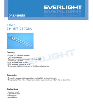
यह दस्तावेज़ एक उच्च चमक वाले सफेद प्रकाश उत्सर्जक डायोड (LED) के विनिर्देशों का विस्तृत विवरण देता है, जिसे विशेष रूप से संकेतक और बैकलाइट अनुप्रयोगों के लिए डिज़ाइन किया गया है। यह उपकरण इंडियम गैलियम नाइट्राइड (InGaN) सेमीकंडक्टर चिप का उपयोग करता है, जो फॉस्फर-भरे परावर्तक कप के साथ संयुक्त है, और नीले प्रकाश के उत्तेजन से सफेद प्रकाश उत्पन्न करता है। LED को उद्योग-मानक T-1 3/4 गोल पैकेज में संलग्न किया गया है, जो आकार और प्रकाश उत्पादन के बीच एक अच्छा संतुलन प्रदान करता है और विभिन्न इलेक्ट्रॉनिक घटकों के लिए उपयुक्त है।
इस उत्पाद का मुख्य लाभ इसकी उच्च दीप्त तीव्रता है, जो मानक ड्राइव धारा पर एक महत्वपूर्ण स्तर तक पहुँच सकती है। इसे उन अनुप्रयोगों के लिए डिज़ाइन किया गया है जिन्हें चमकीली, स्पष्ट दृश्य संकेतन की आवश्यकता होती है। यह उपकरण प्रासंगिक पर्यावरणीय नियमों का अनुपालन करता है और इसमें अंतर्निहित इलेक्ट्रोस्टैटिक डिस्चार्ज (ESD) सुरक्षा है, जो संचालन और असेंबली प्रक्रियाओं के दौरान इसकी विश्वसनीयता को बढ़ाती है।
2. तकनीकी मापदंड: गहन वस्तुनिष्ठ विश्लेषण
2.1 पूर्ण अधिकतम रेटिंग
पूर्ण अधिकतम रेटिंग उन तनाव सीमाओं को परिभाषित करती है जो डिवाइस को स्थायी क्षति पहुंचा सकती हैं। ये मान निरंतर संचालन स्थितियों के लिए लागू नहीं होते।
- निरंतर अग्र धारा (IF)): 30 mA. यह LED एनोड पर लगातार लागू की जा सकने वाली अधिकतम DC धारा है।
- शिखर अग्र धारा (IFP)): 100 mA. यह उच्च धारा केवल स्पंद स्थितियों में अनुमत है, जिसे 1/10 ड्यूटी साइकिल, 1 kHz आवृत्ति के रूप में निर्दिष्ट किया गया है।
- विपरीत वोल्टेज (VR)): 5 V. इस मान से अधिक रिवर्स बायस लागू करने से LED के सेमीकंडक्टर जंक्शन को क्षति पहुँच सकती है।
- पावर डिसिपेशन (Pd)): 110 mW. यह विशिष्ट परिस्थितियों में फॉरवर्ड वोल्टेज और करंट के गुणनफल के रूप में गणना की गई वह अधिकतम शक्ति है जिसे पैकेज ऊष्मा के रूप में व्यय कर सकता है।
- ऑपरेटिंग एवं स्टोरेज तापमान: डिवाइस की रेटेड ऑपरेटिंग तापमान सीमा -40°C से +85°C है, और स्टोरेज तापमान सीमा -40°C से +100°C है।
- ESD सहनशीलता (ह्यूमन बॉडी मॉडल): 4 kV. यह ह्यूमन बॉडी मॉडल मानक के अनुसार इलेक्ट्रोस्टैटिक डिस्चार्ज सुरक्षा स्तर को दर्शाता है।
- सोल्डरिंग तापमान: सोल्डरिंग प्रक्रिया के दौरान, पिन 5 सेकंड तक की अवधि के लिए 260°C के अधिकतम पीक तापमान को सहन कर सकते हैं।
2.2 प्रकाश-विद्युत विशेषताएँ
ये मापदंड मानक परीक्षण स्थितियों में मापे गए हैं: परिवेश का तापमान 25°C, अग्र धारा (IF) 20 mA, यह स्थिति एक सार्वभौमिक संदर्भ बिंदु के रूप में कार्य करती है।
- अग्र वोल्टेज (VF)): सीमा 2.8 V (न्यूनतम) से 3.6 V (अधिकतम) तक, विशिष्ट मान इस सीमा में निहित है। यह निर्दिष्ट धारा प्रवाहित होने पर LED पर वोल्टेज पात है।
- दीप्त तीव्रता (IV)): न्यूनतम मान 3600 mcd (मिलीकैंडेला), अधिकतम 7150 mcd तक। वास्तविक वितरित तीव्रता बाद में विस्तृत बिनिंग प्रणाली द्वारा नियंत्रित होती है।
- देखने का कोण (2θ1/2)): विशिष्ट पूर्ण कोण (वह कोण जिस पर दीप्त तीव्रता अक्षीय शिखर मान की आधी हो जाती है) 50 डिग्री है। यह LED के प्रकाश पुंज के प्रसार की सीमा को परिभाषित करता है।
- क्रोमैटिसिटी निर्देशांक: CIE 1931 क्रोमैटिसिटी आरेख में एक विशिष्ट रंग बिंदु के निर्देशांक x=0.30, y=0.29 हैं। यह LED के आउटपुट प्रकाश की अनुभूत श्वेतता को परिभाषित करता है।
- जेनर डायोड और रिवर्स विशेषताएँ: डिवाइस में एक सुरक्षात्मक जेनर डायोड शामिल हो सकता है, जिसका 5 mA करंट पर रिवर्स ब्रेकडाउन वोल्टेज (Vz) 5.2 V है। 5 V रिवर्स वोल्टेज पर, रिवर्स लीकेज करंट (IR) अधिकतम 50 µA है।
3. ग्रेडिंग प्रणाली विवरण
उत्पादन भिन्नताओं को प्रबंधित करने के लिए, LED को उनके प्रदर्शन के आधार पर विभिन्न बिन में वर्गीकृत किया जाता है। यह डिजाइनरों को ऐसे घटकों का चयन करने में सक्षम बनाता है जो उनके एप्लिकेशन की विशिष्ट न्यूनतम आवश्यकताओं को पूरा करते हैं।
3.1 चमक तीव्रता ग्रेडिंग
IF=20mA स्थिति में मापी गई न्यूनतम और अधिकतम प्रकाश तीव्रता के आधार पर, LED को तीन मुख्य ग्रेड में विभाजित किया गया है। ग्रेड के भीतर तीव्रता सहनशीलता ±10% है।
- Q ग्रेड: 3600 mcd (न्यूनतम) से 4500 mcd (अधिकतम)
- R ग्रेड: 4500 mcd (न्यूनतम) से 5650 mcd (अधिकतम)
- S ग्रेड: 5650 mcd (न्यूनतम) से 7150 mcd (अधिकतम)
3.2 फॉरवर्ड वोल्टेज ग्रेडिंग
LED को IF=20mA पर इसके फॉरवर्ड वोल्टेज ड्रॉप के आधार पर भी ग्रेड किया जाता है, मापन अनिश्चितता ±0.1V है। यह एक समान करंट ड्राइव सर्किट डिजाइन करने में सहायक होता है, खासकर जब कई LED श्रृंखला में जुड़े हों।
- 0 ग्रेड: 2.8 V से 3.0 V
- 1 ग्रेड: 3.0 V से 3.2 V
- 2 ग्रेड:3.2 V से 3.4 V
- 3 ग्रेड:3.4 V से 3.6 V
3.3 रंग ग्रेडिंग
सफेद प्रकाश आउटपुट को CIE क्रोमैटिसिटी डायग्राम पर एक विशिष्ट क्षेत्र में नियंत्रित किया जाता है। यह उत्पाद रंग ग्रेड B5 और B6 से LED को संयोजित करता है, जिससे समूह 7 बनता है। डेटाशीट इन ग्रेडों के लिए कोने के निर्देशांक सीमा प्रदान करती है (उदाहरण के लिए, B5: x 0.287-0.311 के बीच, y 0.276-0.315 के बीच), यह सुनिश्चित करते हुए कि व्हाइट पॉइंट परिभाषित क्षेत्र के भीतर पड़ता है। क्रोमैटिसिटी निर्देशांक की मापन अनिश्चितता ±0.01 है।
4. प्रदर्शन वक्र विश्लेषण
डेटाशीट में कई विशेषता वक्र आरेख शामिल हैं जो विभिन्न परिस्थितियों में डिवाइस के व्यवहार को दर्शाते हैं। एकल-बिंदु विनिर्देशों से परे प्रदर्शन को समझने के लिए यह महत्वपूर्ण है।
- सापेक्ष तीव्रता बनाम तरंगदैर्ध्य: यह स्पेक्ट्रम वितरण वक्र शिखर तरंगदैर्ध्य और फॉस्फर रूपांतरण के कारण होने वाले विस्तारित स्पेक्ट्रम को दर्शाता है, जो सफेद एलईडी की एक विशिष्ट विशेषता है।
- दिशात्मकता आरेख: एक ध्रुवीय आरेख जो प्रकाश तीव्रता के कोणीय वितरण को दर्शाता है, जो 50 डिग्री के विशिष्ट देखने के कोण से संबंधित है।
- फॉरवर्ड करंट बनाम फॉरवर्ड वोल्टेज (I-V कर्व): यह आरेख करंट और वोल्टेज के बीच गैर-रैखिक संबंध दिखाता है। थ्रेसहोल्ड वोल्टेज के बाद वक्र की तीव्र ढलान स्थिर प्रकाश उत्पादन के लिए करंट-नियंत्रित ड्राइव की महत्ता को उजागर करती है।
- सापेक्ष तीव्रता बनाम फॉरवर्ड करंटयह दर्शाता है कि कैसे प्रकाश उत्पादन ड्राइव करंट में वृद्धि के साथ बढ़ता है, आमतौर पर उच्च धाराओं पर दक्षता में गिरावट और तापीय प्रभावों के कारण उप-रैखिक रूप से बढ़ता है।
- क्रोमैटिसिटी निर्देशांक बनाम फॉरवर्ड करंटयह दर्शाता है कि सफेद बिंदु (क्रोमैटिसिटी निर्देशांक) ड्राइव करंट में परिवर्तन के साथ थोड़ा स्थानांतरित हो सकता है, जो रंग-संवेदी अनुप्रयोगों के लिए महत्वपूर्ण है।
- फॉरवर्ड करंट बनाम परिवेश तापमानयह दर्शाता है कि अधिकतम अनुमेय फॉरवर्ड करंट परिवेश तापमान बढ़ने के साथ कैसे कम होता है, यह ताप प्रबंधन और विश्वसनीयता डिजाइन का एक महत्वपूर्ण विचार है।
5. यांत्रिक और पैकेजिंग जानकारी
5.1 पैकेज आयाम
LED एक मानक T-1 3/4 (लगभग 5mm) गोल पैकेज में है जिसमें एक स्पष्ट रेजिन लेंस है। महत्वपूर्ण आयामी विवरण शामिल हैं: सभी आयाम मिलीमीटर में हैं, जब तक अन्यथा निर्दिष्ट न हो, सामान्य सहनशीलता ±0.25mm है; लीड पिच लीड पैकेज बॉडी से बाहर निकलने के बिंदु पर मापी जाती है; रेजिन का फ्लैंज के नीचे अधिकतम प्रोट्रूज़न 1.5mm है। विस्तृत यांत्रिक चित्र कुल व्यास, ऊंचाई, लीड व्यास और पिच के सटीक संख्यात्मक मान प्रदान करते हैं।
5.2 ध्रुवीयता पहचान और स्थापना
पैकेज में एक फ्लैट किनारे वाला फ्लैंज होता है, जो आमतौर पर कैथोड (नकारात्मक) लीड को इंगित करता है। सर्किट कनेक्शन के लिए सही पहचान महत्वपूर्ण है। लीड को प्रिंटेड सर्किट बोर्ड (PCB) पर थ्रू-होल माउंटिंग के लिए डिज़ाइन किया गया है।
6. सोल्डरिंग और असेंबली मार्गदर्शिका
असेंबली प्रक्रिया के दौरान क्षति को रोकने के लिए उचित हैंडलिंग महत्वपूर्ण है।
6.1 पिन फॉर्मिंग
- सील पर तनाव से बचने के लिए मोड़ एपॉक्सी एलईडी बल्ब के आधार से कम से कम 3mm की दूरी पर होना चाहिए।
- आकार देने का कार्य हमेशासोल्डरिंग से पहले soldering.
- पूर्ण। आकार देने की प्रक्रिया में अत्यधिक तनाव एपॉक्सी में दरार या आंतरिक कनेक्शन को नुकसान पहुंचा सकता है।
- लीड कटिंग कमरे के तापमान पर की जानी चाहिए।
- स्थापना तनाव से बचने के लिए पीसीबी होल एलईडी लीड के साथ सटीक रूप से संरेखित होने चाहिए।
6.2 वेल्डिंग शर्तें
थर्मल शॉक को न्यूनतम करने के लिए अनुशंसित पैरामीटर प्रदान किए गए हैं:
- हैंड सोल्डरिंग: सोल्डरिंग आयरन टिप अधिकतम तापमान 300°C (अधिकतम 30W आयरन के लिए), प्रत्येक पिन के लिए अधिकतम सोल्डरिंग समय 3 सेकंड, सोल्डर जॉइंट एपॉक्सी एलईडी से कम से कम 3mm दूरी पर रखें।
- वेव सोल्डरिंग/डिप सोल्डरिंग: प्रीहीट अधिकतम 100°C तक, अधिकतम 60 सेकंड। सोल्डर बाथ तापमान 260°C से अधिक नहीं होना चाहिए, घटक डिप समय अधिकतम 5 सेकंड। 3mm दूरी का नियम यहाँ भी लागू होता है।
6.3 भंडारण शर्तें
नमी अवशोषण (जो सोल्डरिंग के दौरान "पॉपकॉर्न" प्रभाव पैदा कर सकता है) को रोकने के लिए, एलईडी को 30°C से अधिक नहीं और सापेक्ष आर्द्रता (आरएच) 70% से अधिक नहीं के वातावरण में संग्रहित किया जाना चाहिए। शिपमेंट की तारीख से भंडारण जीवन 3 महीने की सिफारिश की जाती है। लंबे समय तक भंडारण (अधिकतम एक वर्ष) के लिए, घटकों को डिसिकेंट के साथ सील्ड मॉइस्चर-बैरियर बैग में, अधिमानतः नाइट्रोजन वातावरण में संग्रहित किया जाना चाहिए।
7. पैकेजिंग और ऑर्डर जानकारी
7.1 पैकेजिंग विनिर्देश
एलईडी पैकेजिंग को स्थैतिक बिजली और भौतिक क्षति से बचाने के लिए डिज़ाइन किया गया है। पहले उन्हें एंटी-स्टैटिक बैग में रखा जाता है। प्रत्येक बैग में 200 से 500 पीस पैक किए जाते हैं। फिर पांच बैग एक आंतरिक बॉक्स में रखे जाते हैं। अंत में, परिवहन के लिए दस आंतरिक बॉक्स एक मुख्य बाहरी कार्टन में पैक किए जाते हैं।
7.2 लेबल विवरण
पैकेजिंग लेबल में कई कोड शामिल होते हैं: CPN (ग्राहक पार्ट नंबर), P/N (निर्माता पार्ट नंबर), QTY (मात्रा), CAT (ल्यूमिनस तीव्रता और फॉरवर्ड वोल्टेज बिनिंग संयोजन कोड), HUE (रंग ग्रेड कोड), REF (संदर्भ) और LOT No. (ट्रेस करने योग्य उत्पादन बैच नंबर)।
7.3 मॉडल नामकरण नियम
पार्ट नंबर 334-15/T1C5-7 QSA एक विशिष्ट संरचना का पालन करता है। प्रत्यय कोड (डेटाशीट में बॉक्स द्वारा दर्शाया गया) निर्माता के चयन मार्गदर्शिका के अनुसार विशिष्ट ल्यूमिनस तीव्रता ग्रेड, फॉरवर्ड वोल्टेज ग्रेड और अन्य वैकल्पिक विशेषताओं का चयन करने की अनुमति देता है।
8. अनुप्रयोग सुझाव
8.1 विशिष्ट अनुप्रयोग परिदृश्य
डेटाशीट में सूचीबद्ध अनुसार, यह उच्च-तीव्रता वाला व्हाइट LED उपयुक्त है:
- सूचना पैनल और साइनेज: जहाँ चमकीले, स्वतंत्र पिक्सेल या संकेतक की आवश्यकता हो।
- ऑप्टिकल इंडिकेटर: औद्योगिक उपकरण, उपभोक्ता इलेक्ट्रॉनिक्स या कंट्रोल पैनल पर स्थिति दर्शाने वाली लाइट।
- बैकलाइटिंग: छोटे एलसीडी डिस्प्ले, फिल्म स्विच पैनल या सजावटी प्रकाश व्यवस्था के लिए उपयोग किया जाता है जहाँ समान प्रकाश की आवश्यकता होती है, आमतौर पर एक सरणी के रूप में उपयोग किया जाता है।
- मार्कर लाइट: ऐसे उपकरणों, वाहनों या सुरक्षा अनुप्रयोगों में उपयोग किया जाता है जहाँ उच्च दृश्यता की आवश्यकता होती है।
8.2 डिज़ाइन विचार
- करंट ड्राइव: सीरीज़ करंट-लिमिटिंग रेसिस्टर या कॉन्स्टेंट-करंट ड्राइव सर्किट का उपयोग अवश्य करें। घातीय I-V संबंध के कारण, वोल्टेज स्रोत से सीधे LED को ड्राइव करने से यह क्षतिग्रस्त हो सकता है।
- थर्मल मैनेजमेंट: अपेक्षाकृत कम शक्ति के बावजूद, पर्याप्त वेंटिलेशन या हीट सिंक सुनिश्चित करना दीर्घकालिक प्रकाश उत्पादन और विश्वसनीयता बनाए रखने के लिए बहुत महत्वपूर्ण है, खासकर उच्च परिवेश तापमान या ड्राइव करंट पर।
- ऑप्टिकल डिज़ाइन: 50-डिग्री व्यूइंग एंगल एक विस्तृत बीम प्रदान करता है। अधिक केंद्रित प्रकाश के लिए, लेंस या लाइट पाइप जैसे सेकेंडरी ऑप्टिकल घटकों की आवश्यकता हो सकती है।
- बिनिंग चयन: ऐसे अनुप्रयोगों के लिए जहां कई LEDs के बीच समान चमक या रंग प्राप्त करना आवश्यक है, सख्त तीव्रता बिन (जैसे, केवल S बिन) और विशिष्ट वोल्टेज/रंग समूह निर्दिष्ट करने की सिफारिश की जाती है।
9. तकनीकी तुलना एवं विभेदीकरण
सामान्य 5mm व्हाइट एलईडी की तुलना में, यह उत्पाद काफी अधिक ल्यूमिनस तीव्रता प्रदान करता है, जिससे यह उन अनुप्रयोगों के लिए उपयुक्त हो जाता है जहाँ उत्कृष्ट चमक की आवश्यकता होती है। अनग्रेडेड या ढीले ग्रेडेड विकल्पों की तुलना में, तीव्रता और फॉरवर्ड वोल्टेज के लिए एक स्पष्ट ग्रेडिंग प्रणाली शामिल है, जो उत्पादन बैचों को अधिक पूर्वानुमेयता और स्थिरता प्रदान करती है। अंतर्निहित ESD सुरक्षा (4kV HBM) असेंबली वातावरण में मजबूती बढ़ाती है। रंग ग्रेड (B5+B6) का विशिष्ट संयोजन एक विशिष्ट व्हाइट पॉइंट के लिए है, जो अन्य उत्पादों द्वारा प्रदान किए गए ठंडे या गर्म व्हाइट पॉइंट से भिन्न हो सकता है।
10. सामान्य प्रश्न (तकनीकी मापदंडों पर आधारित)
10.1 निरंतर अग्र धारा और शिखर अग्र धारा में क्या अंतर है?
निरंतर फॉरवर्ड करंट (30 mA) सुरक्षित, दीर्घकालिक संचालन के लिए अधिकतम डीसी करंट है। पीक फॉरवर्ड करंट (100 mA) एक अल्पकालिक, पल्स रेटिंग है, जिसका उपयोग संक्षिप्त अवधि (उदाहरण के लिए, मल्टीप्लेक्स डिस्प्ले में) के लिए किया जा सकता है, लेकिन डीसी ऑपरेशन में क्षण भर के लिए भी इससे अधिक नहीं होना चाहिए, अन्यथा अत्यधिक गर्मी और त्वरित क्षरण हो सकता है।
10.2 उचित करंट-सीमित रोकनेवाला कैसे चुनें?
ओम के नियम का उपयोग करें: R = (Vपावर सप्लाई- VF) / IF। रूढ़िवादी डिजाइन के लिए, यह सुनिश्चित करने हेतु कि घटकों में भिन्नता होने पर भी धारा कभी 20mA से अधिक न हो, डेटाशीट में दिए गए अधिकतम VFमान (3.6V) का उपयोग करें। उदाहरण के लिए, 5V पावर सप्लाई के साथ: R = (5V - 3.6V) / 0.020A = 70 ओम। निकटतम मानक मान (68 या 75 ओम) चुनें और उसकी पावर रेटिंग जांचें (P = I2R)।
10.3 क्या मैं इस LED का उपयोग बाहरी स्थानों में कर सकता हूँ?
ऑपरेटिंग तापमान रेंज (-40°C से +85°C) इसके कई बाहरी वातावरणों में उपयोग की अनुमति देती है। हालांकि, यह पैकेज विशेष रूप से वाटरप्रूफिंग या यूवी डिग्रेडेशन के लिए रेटेड नहीं है। सीधे बाहरी संपर्क के लिए, नमी और सूर्य के प्रकाश से सुरक्षा हेतु अतिरिक्त पर्यावरणीय संरक्षण (जैसे कन्फॉर्मल कोटिंग, सील एन्क्लोजर) की आवश्यकता होती है।
11. व्यावहारिक अनुप्रयोग उदाहरण
बहु-एलईडी स्थिति संकेतक पैनल डिज़ाइन:एक नियंत्रण पैनल को विभिन्न मशीन कार्यों की परिचालन स्थिति दर्शाने के लिए 20 चमकीले श्वेत एलईडी की आवश्यकता है। सौंदर्य और स्पष्टता के लिए समान चमक महत्वपूर्ण है।
- सर्किट डिज़ाइन: डिज़ाइनर ने 12V पावर रेल से सभी एलईडी को समानांतर में चलाने का चयन किया। प्रत्येक एलईडी शाखा का अपना करंट-लिमिटिंग रेसिस्टर है। अधिकतम VF3.6V और लक्ष्य IF20mA का उपयोग करते हुए, रेसिस्टर मान (12V - 3.6V)/0.02A = 420 ओम है। प्रत्येक शाखा के लिए 430 ओम, 1/4W रेसिस्टर चुना गया।
- बिनिंग चयन: स्थिरता सुनिश्चित करने के लिए, डिज़ाइनर ने एस-बिन (उच्चतम तीव्रता) वाले एलईडी निर्दिष्ट किए, और रंग व चमक अंतर को न्यूनतम करने के लिए उत्पादन के एक ही बैच और रंग समूह (समूह 7) से आने की आवश्यकता रखी।
- पीसीबी लेआउट: पैकेज ड्राइंग के अनुसार पिन पिच पर ड्रिल करें। वेव सोल्डरिंग के दौरान सोल्डर विकिंग से बचने के लिए LED लैंप बॉडी के चारों ओर कम से कम 3mm त्रिज्या का नो-गो क्षेत्र बनाए रखें।
- असेंबली: असेंबलर हैंड सोल्डरिंग गाइडलाइन्स का पालन करते हैं, 300°C पर सेट तापमान-नियंत्रित सोल्डरिंग आयरन का उपयोग करते हैं, और प्रत्येक सोल्डर जोड़ को 3 सेकंड के भीतर पूरा करते हैं।
12. कार्य सिद्धांत का संक्षिप्त परिचय
यह एक फॉस्फर-कन्वर्टेड व्हाइट LED है। इसका मूल इंडियम गैलियम नाइट्राइड (InGaN) से बना एक सेमीकंडक्टर चिप है। जब फॉरवर्ड वोल्टेज लगाया जाता है, तो इलेक्ट्रॉन और होल चिप के एक्टिव रीजन में पुनर्संयोजित होते हैं, जिससे फोटॉन उत्सर्जित होते हैं। InGaN सामग्री को ब्लू लाइट (आमतौर पर 450-455 nm के आसपास) उत्सर्जित करने के लिए डिज़ाइन किया गया है। यह ब्लू लाइट सीधे उत्सर्जित नहीं होती है। इसके बजाय, यह चिप के चारों ओर रिफ्लेक्टर कप के अंदर जमा फॉस्फर सामग्री (उदाहरण के लिए, सेरियम-डोप्ड यिट्रियम एल्यूमीनियम गार्नेट, YAG:Ce) की एक परत पर पड़ती है। फॉस्फर ब्लू फोटॉन के एक हिस्से को अवशोषित करता है और एक व्यापक स्पेक्ट्रम पर प्रकाश को फिर से उत्सर्जित करता है, मुख्य रूप से पीला प्रकाश। मानव आंख द्वारा अनुभव किया गया शेष बिना अवशोषित ब्लू लाइट और फॉस्फर द्वारा उत्पन्न पीले प्रकाश का मिश्रण सफेद प्रकाश के रूप में माना जाता है। सटीक रंग तापमान (कूल व्हाइट, न्यूट्रल व्हाइट, वार्म व्हाइट) फॉस्फर परत की संरचना और मोटाई द्वारा निर्धारित होता है।
13. प्रौद्योगिकी रुझान
इस प्रकार के LED के पीछे की तकनीक लगातार विकसित हो रही है। उद्योग के समग्र रुझानों में शामिल हैं:
- दक्षता वृद्धि (लुमेन प्रति वाट)चिप एपिटैक्सी, प्रकाश निष्कर्षण और फॉस्फर दक्षता में निरंतर सुधार के कारण समान विद्युत इनपुट पर उच्च प्रकाश आउटपुट प्राप्त होता है, जिससे ऊर्जा खपत कम होती है।
- रंग प्रतिपादन में सुधारहालांकि यह डेटाशीट एकल श्वेत बिंदु निर्दिष्ट करती है, नए उत्पाद आमतौर पर उच्च कलर रेंडरिंग इंडेक्स (CRI) मान प्राप्त करने के लिए बहु-फॉस्फर मिश्रण (जैसे, लाल फॉस्फर जोड़ना) का उपयोग करते हैं, जिससे रंग प्रकाश में अधिक प्राकृतिक दिखते हैं।
- लघुरूपणहालांकि T-1 3/4 पैकेज अभी भी लोकप्रिय है, उच्च घनत्व वाले अनुप्रयोगों की मांग को पूरा करने के लिए छोटे सरफेस माउंट डिवाइस (SMD) पैकेज (जैसे 3535, 3030, 2835) की ओर एक व्यापक प्रवृत्ति है, हालांकि बड़े थ्रू-होल प्रकारों की तुलना में आमतौर पर एकल पैकेज के कुल प्रकाश आउटपुट पर समझौता करना पड़ता है।
- उच्च विश्वसनीयता और जीवनकालपैकेजिंग सामग्री, चिप अटैचमेंट और वायर बॉन्डिंग तकनीकों में प्रगति एलईडी की रेटेड लाइफ (L70/B50) को लगातार और आगे बढ़ा रही है, जिससे ये अधिक मांग वाले अनुप्रयोगों के लिए उपयुक्त होते जा रहे हैं।
LED विनिर्देश शब्दावली का विस्तृत विवरण
LED तकनीकी शब्दावली की पूर्ण व्याख्या
1. प्रकाश-विद्युत प्रदर्शन के मुख्य संकेतक
| शब्दावली | इकाई/प्रतिनिधित्व | सामान्य व्याख्या | यह महत्वपूर्ण क्यों है |
|---|---|---|---|
| दीप्त प्रभावकारिता (Luminous Efficacy) | lm/W (लुमेन प्रति वाट) | प्रति वाट विद्युत ऊर्जा से उत्सर्जित दीप्त फ्लक्स, जितना अधिक होगा उतनी अधिक ऊर्जा बचत। | यह सीधे तौर पर प्रकाश उपकरण की ऊर्जा दक्षता श्रेणी और बिजली लागत निर्धारित करता है। |
| दीप्त फ्लक्स (Luminous Flux) | lm (Lumen) | प्रकाश स्रोत द्वारा उत्सर्जित कुल प्रकाश मात्रा, जिसे आमतौर पर "चमक" कहा जाता है। | यह निर्धारित करता है कि लैंप पर्याप्त रूप से चमकीला है या नहीं। |
| Viewing Angle | ° (डिग्री), जैसे 120° | वह कोण जिस पर प्रकाश तीव्रता आधी रह जाती है, यह प्रकाश पुंज की चौड़ाई निर्धारित करता है। | प्रकाश के दायरे और एकरूपता को प्रभावित करता है। |
| रंग तापमान (CCT) | K (केल्विन), जैसे 2700K/6500K | प्रकाश के रंग की गर्माहट या ठंडापन, कम मान पीला/गर्म, उच्च मान सफेद/ठंडा। | प्रकाश व्यवस्था के वातावरण और उपयुक्त परिदृश्य का निर्धारण करता है। |
| रंग प्रतिपादन सूचकांक (CRI / Ra) | इकाईहीन, 0–100 | प्रकाश स्रोत द्वारा वस्तुओं के वास्तविक रंगों को पुन: प्रस्तुत करने की क्षमता, Ra≥80 उत्तम माना जाता है। | रंग सत्यता को प्रभावित करता है, शॉपिंग मॉल, आर्ट गैलरी जैसे उच्च आवश्यकता वाले स्थानों में प्रयुक्त। |
| क्रोमैटिकिटी टॉलरेंस (SDCM) | मैकएडम एलिप्स स्टेप्स, जैसे "5-step" | रंग एकरूपता का मात्रात्मक सूचक, स्टेप्स जितने कम होंगे, रंग उतने ही अधिक सुसंगत होंगे। | एक ही बैच के लैंपों के रंग में कोई अंतर नहीं होने की गारंटी। |
| प्रमुख तरंगदैर्ध्य (Dominant Wavelength) | nm (नैनोमीटर), उदाहरण के लिए 620nm (लाल) | रंगीन LED के रंग से संबंधित तरंगदैर्ध्य मान। | लाल, पीले, हरे आदि एकल-रंग LED के रंगत (ह्यू) को निर्धारित करता है। |
| स्पेक्ट्रम वितरण (Spectral Distribution) | तरंगदैर्ध्य बनाम तीव्रता वक्र | LED द्वारा उत्सर्जित प्रकाश की विभिन्न तरंगदैर्ध्य पर तीव्रता वितरण प्रदर्शित करता है। | रंग प्रतिपादन एवं रंग गुणवत्ता को प्रभावित करता है। |
दो, विद्युत मापदंड
| शब्दावली | प्रतीक | सामान्य व्याख्या | डिज़ाइन संबंधी विचार |
|---|---|---|---|
| फॉरवर्ड वोल्टेज (Forward Voltage) | Vf | LED को चालू करने के लिए आवश्यक न्यूनतम वोल्टेज, एक प्रकार का "स्टार्ट-अप थ्रेशोल्ड"। | ड्राइव पावर सप्लाई वोल्टेज ≥ Vf होना चाहिए, कई LED को श्रृंखला में जोड़ने पर वोल्टेज जुड़ जाता है। |
| फॉरवर्ड करंट (Forward Current) | If | LED को सामान्य रूप से चमकने के लिए आवश्यक धारा मान। | आमतौर पर स्थिर धारा ड्राइव का उपयोग किया जाता है, धारा चमक और आयु निर्धारित करती है। |
| अधिकतम स्पंद धारा (Pulse Current) | Ifp | अल्प अवधि में सहन करने योग्य शिखर धारा, डिमिंग या फ्लैश के लिए उपयोग की जाती है। | स्पंद चौड़ाई और ड्यूटी साइकल को सख्ती से नियंत्रित किया जाना चाहिए, अन्यथा अत्यधिक ताप से क्षति होगी। |
| रिवर्स वोल्टेज (Reverse Voltage) | Vr | LED द्वारा सहन की जा सकने वाली अधिकतम रिवर्स वोल्टेज, इससे अधिक होने पर ब्रेकडाउन हो सकता है। | सर्किट में रिवर्स कनेक्शन या वोल्टेज स्पाइक को रोकने की आवश्यकता होती है। |
| थर्मल रेजिस्टेंस (Thermal Resistance) | Rth (°C/W) | चिप से सोल्डर पॉइंट तक गर्मी के प्रवाह का प्रतिरोध, कम मान बेहतर ताप अपव्यय दर्शाता है। | उच्च तापीय प्रतिरोध के लिए मजबूत शीतलन डिजाइन की आवश्यकता होती है, अन्यथा जंक्शन तापमान बढ़ जाता है। |
| इलेक्ट्रोस्टैटिक डिस्चार्ज इम्यूनिटी (ESD Immunity) | V (HBM), जैसे 1000V | इलेक्ट्रोस्टैटिक शॉक प्रतिरोध क्षमता, उच्च मान का अर्थ है स्थैतिक बिजली से क्षति की संभावना कम। | उत्पादन में इलेक्ट्रोस्टैटिक सुरक्षा उपाय आवश्यक हैं, विशेष रूप से उच्च संवेदनशीलता वाले LED के लिए। |
तीन, ताप प्रबंधन और विश्वसनीयता
| शब्दावली | प्रमुख संकेतक | सामान्य व्याख्या | प्रभाव |
|---|---|---|---|
| जंक्शन तापमान (Junction Temperature) | Tj (°C) | LED चिप के अंदर का वास्तविक कार्य तापमान। | प्रत्येक 10°C कमी से, जीवन दोगुना हो सकता है; अत्यधिक तापमान से प्रकाश क्षय और रंग विस्थापन होता है। |
| प्रकाश क्षय (Lumen Depreciation) | L70 / L80 (घंटे) | चमक प्रारंभिक मूल्य के 70% या 80% तक गिरने में लगने वाला समय। | सीधे LED के "उपयोगी जीवन" को परिभाषित करता है। |
| लुमेन रखरखाव दर (Lumen Maintenance) | % (जैसे 70%) | एक निश्चित अवधि के उपयोग के बाद शेष चमक का प्रतिशत। | दीर्घकालिक उपयोग के बाद चमक बनाए रखने की क्षमता को दर्शाता है। |
| Color Shift | Δu′v′ या MacAdam Ellipse | उपयोग के दौरान रंग में परिवर्तन की मात्रा। | प्रकाश दृश्य की रंग संगति को प्रभावित करता है। |
| थर्मल एजिंग (Thermal Aging) | सामग्री प्रदर्शन में गिरावट | दीर्घकालिक उच्च तापमान के कारण एनकैप्सुलेशन सामग्री का क्षरण। | चमक में कमी, रंग परिवर्तन या ओपन सर्किट विफलता का कारण बन सकता है। |
चार, पैकेजिंग और सामग्री
| शब्दावली | सामान्य प्रकार | सामान्य व्याख्या | विशेषताएँ और अनुप्रयोग |
|---|---|---|---|
| पैकेजिंग प्रकार | EMC, PPA, सिरेमिक | चिप की सुरक्षा करने वाली और प्रकाशिकी व तापीय इंटरफेस प्रदान करने वाली आवरण सामग्री। | EMC ताप प्रतिरोधी अच्छा, लागत कम; सिरेमिक ताप अपव्यय उत्कृष्ट, जीवनकाल लंबा। |
| चिप संरचना | फॉरवर्ड माउंट, फ्लिप चिप (Flip Chip) | चिप इलेक्ट्रोड व्यवस्था विधि। | फ्लिप चिप में बेहतर हीट डिसिपेशन और उच्च प्रकाश दक्षता होती है, जो उच्च शक्ति के लिए उपयुक्त है। |
| फॉस्फर कोटिंग | YAG, सिलिकेट, नाइट्राइड | नीले प्रकाश चिप पर लगाया जाता है, जिसका कुछ भाग पीले/लाल प्रकाश में परिवर्तित होकर सफेद प्रकाश बनाता है। | विभिन्न फॉस्फर प्रकाश दक्षता, रंग तापमान और रंग प्रतिपादन को प्रभावित करते हैं। |
| लेंस/ऑप्टिकल डिज़ाइन | समतल, माइक्रोलेंस, कुल आंतरिक परावर्तन | पैकेजिंग सतह की प्रकाशिक संरचना, जो प्रकाश वितरण को नियंत्रित करती है। | प्रकाश उत्सर्जन कोण और प्रकाश वितरण वक्र निर्धारित करता है। |
पाँच, गुणवत्ता नियंत्रण और ग्रेडिंग
| शब्दावली | ग्रेडिंग सामग्री | सामान्य व्याख्या | उद्देश्य |
|---|---|---|---|
| ल्यूमिनस फ्लक्स ग्रेडिंग | कोड जैसे 2G, 2H | चमक के स्तर के अनुसार समूहों में विभाजित, प्रत्येक समूह का न्यूनतम/अधिकतम लुमेन मान होता है। | एक ही बैच के उत्पादों की चमक सुनिश्चित करें। |
| वोल्टेज ग्रेडिंग | कोड जैसे 6W, 6X | फॉरवर्ड वोल्टेज रेंज के अनुसार समूहीकरण। | ड्राइव पावर मिलान की सुविधा के लिए, सिस्टम दक्षता बढ़ाने के लिए। |
| रंग ग्रेडिंग | 5-चरण MacAdam दीर्घवृत्त | रंग निर्देशांक के अनुसार समूहीकरण करें, यह सुनिश्चित करते हुए कि रंग अत्यंत सीमित सीमा के भीतर आता है। | रंग एकरूपता सुनिश्चित करें, एक ही प्रकाश स्रोत के भीतर रंग में असमानता से बचें। |
| रंग तापमान श्रेणीकरण | 2700K, 3000K, आदि। | रंग तापमान के अनुसार समूहीकरण करें, प्रत्येक समूह की अपनी संबंधित निर्देशांक सीमा होती है। | विभिन्न परिदृश्यों की रंग तापमान आवश्यकताओं को पूरा करता है। |
छह, परीक्षण और प्रमाणन
| शब्दावली | मानक/परीक्षण | सामान्य व्याख्या | महत्व |
|---|---|---|---|
| LM-80 | लुमेन रखरखाव परीक्षण | निरंतर तापमान परिस्थितियों में लंबे समय तक जलाकर, चमक क्षय डेटा रिकॉर्ड करें। | LED जीवनकाल का अनुमान लगाने के लिए (TM-21 के साथ संयुक्त)। |
| TM-21 | जीवनकाल प्रक्षेपण मानक | LM-80 डेटा के आधार पर वास्तविक उपयोग की स्थितियों में जीवनकाल का अनुमान लगाना। | वैज्ञानिक जीवनकाल पूर्वानुमान प्रदान करना। |
| IESNA Standard | Illuminating Engineering Society Standard | Optical, electrical, and thermal testing methods are covered. | Industry-recognized testing basis. |
| RoHS / REACH | Environmental Certification | उत्पाद में हानिकारक पदार्थ (जैसे सीसा, पारा) नहीं होने का आश्वासन दें। | अंतरराष्ट्रीय बाजार में प्रवेश की पात्रता शर्तें। |
| ENERGY STAR / DLC | ऊर्जा दक्षता प्रमाणन | प्रकाश उत्पादों के लिए ऊर्जा दक्षता और प्रदर्शन प्रमाणन। | आमतौर पर सरकारी खरीद, सब्सिडी कार्यक्रमों में उपयोग किया जाता है, बाजार प्रतिस्पर्धा बढ़ाने के लिए। |