Table of Contents
- 1. Product Overview
- 1.1 Core Advantages and Target Market
- 2. Uchambuzi wa Vigezo vya Kiufundi
- 2.1 Viwango Vya Juu Kabisa
- 2.2 Electro-Optical Characteristics
- 2.3 Thermal Characteristics
- 3. Binning System Description
- 3.1 Luminous Intensity Binning
- 3.2 Dominant Wavelength Binning
- 4. Performance Curve Analysis
- 4.1 Relative Luminous Intensity vs. Forward Current
- 4.2 Relative Luminous Intensity vs. Ambient Temperature
- 4.3 Forward Current vs. Forward Voltage (I-V Curve)
- 4.4 Spectral Distribution
- 4.5 Radiation Pattern
- 5. Mechanical and Packaging Information
- 5.1 Package Dimensions and Pad Pattern
- 5.2 Polarity Identification
- 6. Soldering and Assembly Guide
- 6.1 Mkunjo wa Joto wa Reflow Soldering
- 6.2 Mambo Muhimu ya Kuzingatia
- 7. Ufungaji na Taarifa za Kuagiza
- 7.1 Moisture Sensitivity and Storage
- 7.2 Tape and Reel Specifications
- 7.3 Label Description
- 8. Application Design Considerations
- 8.1 Typical Application Circuit
- 。
- For light guide applications, top-view emission through the PCB is the ideal choice. The LED should be placed directly beneath the input surface of the light guide. A wide viewing angle helps capture most of the emitted light into the light guide. The gap between the LED lens and the light guide should be minimized, and optical coupling materials (e.g., silicone, clear adhesive) can be used to reduce Fresnel reflection losses at the air gap.
- Although it is a small-signal device, thermal management can improve its lifespan. Use the recommended pad size. Connecting the thermal pad (if present) or the cathode/anode pad to a larger copper area on the PCB helps with heat dissipation. Thermal vias under the package can transfer heat to inner or bottom layers. Avoid placing the LED near other heat-generating components.
- Kutimiza utofautishaji. Ikilinganishwa na LED za kawaida za mtazamo wa upande au pembe ya kulia, muundo huu unarahisisha ujumuishaji wa kiufundi na boriti ya kuongoza mwanga, na kuondoa hitaji la mikunjo changamano au mageuzi ya digrii 90 kwenye mwongozo wa mwanga. Kioakisi cha ndani kilichojumuishwa ni kipengele kilichoundwa mahsusi ili kuboresha ufanisi wa macho wa njia hii ya kuunganisha. Kwa kifurushi cha mtazamo wa juu, pembe ya mtazamo ya digrii 120 ni pana isiyo ya kawaida, ikitoa muonekano bora wa mbali na mhimili kuliko washindani wengi. Inalingana na viwango vya kisasa vya uuzaji wa halojeni na joto la juu (bila risasi), na kuifanya ifae kwa utengenezaji wa kisasa wa elektroniki unaolenga mazingira.
- Ina husika zaidi katika mechi ya rangi ya matumizi ya kuona.
- Mfumo safi na unaotegemewa wa viashiria vya taa, wenye mwangaza na rangi thabiti, shukrani kwa faida maalum ya kuunganisha kioo ya 65-21 LED.
1. Product Overview
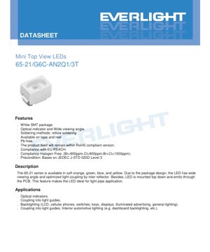
Mfululizo wa 65-21 unawakilisha familia ya LED ndogo za kuangalia juu zilizoundwa kwa matumizi ya teknolojia ya kukanyaga uso (SMT). Aina hii maalum hutambuliwa kupitia kiambishi chake kinachoashiria kiwango, na inatoa mwanga wa kijani-kimanjano mkali. Dhamira yake ya msingi ya muundo inazunguka usanidi wa usakinishaji kutoka juu kwenda chini, ambapo mwanga hutolewa kupitia bodi ya mzunguko iliyochapishwa (PCB). Muundo huu wa kipekee, pamoja na kioakisi cha ndani kilichojumuishwa, unakusudiwa kuboresha kuunganishwa kwa pato la mwanga, na kufanya vipengele hivi vifae hasa kwa matumizi yanayotumia nguzo za kuongoza mwanga au miongozo ya mwanga.
该封装为紧凑的白色表面贴装器件。一个关键性能特点是其异常宽广的视角,定义为120度(半峰全宽,2θ1/2)。这种宽广的发射轮廓确保了从各个角度都能获得高可见度,这是指示灯应用的关键因素。该产品符合主要的环境和安全指令,包括RoHS(有害物质限制)、欧盟REACH法规,并且采用无卤素制造(溴<900ppm,氯<900ppm,总和<1500ppm)。它以编带盘装形式提供,兼容自动化贴片组装工艺。
1.1 Core Advantages and Target Market
The primary advantages of the 65-21 series stem from its mechanical and optical design. Top-view, through-PCB light emission is its defining feature, enabling efficient coupling with light pipes without the need for side-emitting or right-angle mounting. The integrated reflector within the package enhances light extraction and directionality. The 120-degree wide viewing angle provides excellent omnidirectional visibility. The SMT package allows for high-density PCB layouts and is compatible with standard reflow soldering processes.
Matumizi yanayolengwa ni mbalimbali, hasa katika nyanja ambapo ukubwa mdogo, uaminifu wa kiashiria, na ufanisi wa kuongoza mwanga ni muhimu sana. Hizi ni pamoja na: taa za hali ya macho kwenye vifaa vya matumizi ya kaya na viwanda; mwanga wa nyuma wa skrini za kioevu (LCD), kibodi, swichi, na dashibodi; taa za jumla za matangazo na ishara; na taa za ndani za magari, kama vile mwanga wa nyuma wa dashibodi. Sehemu hii imetayarishwa kulingana na kiwango cha JEDEC J-STD-020D Level 3, ikionyesha kuwa inafaa kwa mchakato wa kawaida wa kuunganishia kibiashara.
2. Uchambuzi wa Vigezo vya Kiufundi
Sehemu hii inatoa ufafanuzi wa kina na wa kitu cha vigezo muhimu vya umeme, vya mwanga na vya joto vilivyofafanuliwa katika hati ya maelezo. Kuelewa mipaka na sifa hizi ni muhimu kwa usanifu wa saketi unaoaminika na kuhakikisha utendaji wa muda mrefu wa LED.
2.1 Viwango Vya Juu Kabisa
Absolute Maximum Ratings hufafanua mipaka ya mkazo ambayo inaweza kusababisha uharibifu wa kudumu wa LED. Haya si hali ya kawaida ya uendeshaji.
- Reverse Voltage (VR):12V. Exceeding this voltage in the reverse bias direction may cause junction breakdown.
- Continuous Forward Current (IF):25mA. Hii ndiyo mkondo wa moja kwa moja wa juu zaidi unaoweza kutumika kwa mfululizo.
- Mkondo wa kilele wa mbele (IFP):60mA. Hii inaruhusiwa tu chini ya hali ya msukumo (uwiano wa wajibu 10%, masafa 1kHz), haipaswi kutumika kwa operesheni ya mkondo wa moja kwa moja.
- Power Consumption (Pd):60mW. The maximum power that the package can dissipate in the form of heat, calculated as forward voltage (VF) × forward current (IF).
- Junction Temperature (Tj):115°C. Joto la juu kabisa linaloruhusiwa na chip ya semiconductor yenyewe.
- Joto la kufanya kazi na la uhifadhi:-40°C hadi +85°C (kufanya kazi), -40°C hadi +90°C (uhifadhi).
- Utoaji wa umeme tuli (ESD):2000V (Human Body Model). Proper ESD handling procedures must be followed.
- Soldering Temperature:For reflow soldering, the peak temperature is specified as 260°C for a maximum of 10 seconds. For hand soldering, a maximum of 3 seconds per pin at 350°C is permitted.
2.2 Electro-Optical Characteristics
These parameters are measured under standard test conditions of 25°C ambient temperature and a forward current (IF) of 20mA, unless otherwise specified.
- Luminous Intensity (IV):Mbalimbali kutoka kiwango cha chini cha 36 millicandela (mcd) hadi kiwango cha juu cha 90 mcd. Kwa kuwa vifaa vimepangwa katika makundi, hakuna thamani ya kawaida maalum. Toleransi inayotumika ni ±11%.
- Pembe ya mtazamo (2θ1/2):120 digrii. Hii ni upana wa pembe ambapo kiwango cha mwanga angalau ni nusu ya kiwango cha kilele kilichopimwa kwenye digrii 0 (mhimli).
- Peak wavelength (λp):Approximately 575 nanometers (nm). This is the wavelength at which the spectral power distribution reaches its maximum value.
- Dominant wavelength (λd):Ranging from 569.5 nm to 577.5 nm. This is the single wavelength perceived by the human eye as the LED's color and is a key parameter for color binning. The tolerance is ±1nm.
- Spectral bandwidth (Δλ):Approximately 20 nm. This indicates spectral purity; the smaller the bandwidth, the closer the color is to monochromatic.
- Forward Voltage (VF):At 20mA, ranges from 1.75V to 2.35V. Tolerance is ±0.1V. This is crucial for designing the current-limiting resistor in series with the LED.
- Reverse Current (IR):When a reverse bias of 12V is applied, the maximum current is 10 microamperes (μA).
2.3 Thermal Characteristics
Although not explicitly listed in a separate table, thermal management is addressed through power dissipation (Pd) and junction temperature (TjThe rating is reflected. The forward current derating curve graphically shows how the maximum allowable continuous forward current must be reduced when the ambient temperature exceeds 25°C to prevent exceeding the 115°C junction temperature limit. For high-current or high ambient temperature applications, an effective PCB layout with sufficient thermal design is required.
3. Binning System Description
To ensure color and brightness consistency in production, LEDs are sorted into different bins. The 65-21 series uses independent binning for luminous intensity and dominant wavelength.
3.1 Luminous Intensity Binning
Kiwango cha mwanga kinapopimwa kwa IF= 20mA, kinagawanywa katika viwango vinne tofauti (N2, P1, P2, Q1). Kila kiwango kinashughulikia masafa maalum:
- N2:36 mcd to 45 mcd
- P1:45 mcd to 57 mcd
- P2:57 mcd to 72 mcd
- Q1:72 mcd to 90 mcd
The part number (e.g., G6C-AN2Q1/3T) contains codes specifying the intensity bin and wavelength bin to which the device belongs, allowing designers to select parts with tight performance tolerances for their application.
3.2 Dominant Wavelength Binning
The dominant wavelength, which defines the perceived yellow-green color, is binned within Group A. It is divided into four codes (C16 to C19), each spanning a 2nm range:
- C16:569.5 nm to 571.5 nm
- C17:571.5 nm to 573.5 nm
- C18:573.5 nm to 575.5 nm
- C19:575.5 nm to 577.5 nm
This precise binning ensures minimal color variation among LEDs within a single component, which is crucial for applications such as multi-LED backlights or indicator arrays.
4. Performance Curve Analysis
Mwongozo wa maelezo unatoa mikunjo kadhaa ya sifa, inayoonyesha tabia ya LED chini ya hali tofauti. Hizi ni muhimu kwa kuzingatia muundo wa hali ya juu.
4.1 Relative Luminous Intensity vs. Forward Current
Mkunjio huu unaonyesha kuwa ukubwa wa mwanga haufuati uwiano wa mstari sawa na mkondo wa mbele. Ingawa ukubwa huongezeka kadri mkondo unavyoongezeka, katika mikondo ya juu zaidi, uhusiano huelekea kuwa chini ya mstari kwa sababu ya joto la kiungo kuongezeka na ufanisi kupungua. Kufanya kazi kwa mikondo inayozidi kwa kiasi kikubwa mkondo wa kupima unaopendekezwa wa 20mA, kunaweza kusababisha faida ya mwangaza kupungua na kuongeza kiwango cha kuzeeka.
4.2 Relative Luminous Intensity vs. Ambient Temperature
Mchoro huu unaonyesha mgawo hasi wa joto wa pato la mwanga. Kadri joto la mazingira linavyopanda, pato la mwanga la LED linapungua. Hii ni sifa ya msingi ya chanzo cha mwanga cha semiconductor. Mkunjo huu unawawezesha wabunifu kukadiria upotezaji wa mwangaza katika mazingira ya joto la juu na kufanya urekebishaji ikiwa ni lazima.
4.3 Forward Current vs. Forward Voltage (I-V Curve)
The I-V curve is inherently exponential, which is a typical characteristic of a diode. A small increase in forward voltage results in a large increase in forward current. This highlights the extreme importance of using a current-limiting device (almost always a resistor) in series with an LED when powered by a voltage source. Driving an LED with a constant voltage will lead to thermal runaway and damage.
4.4 Spectral Distribution
The spectral distribution graph shows the relative optical power emitted at different wavelengths. For this bright yellow-green LED, the peak is around 575nm, with a typical full width at half maximum (FWHM) of 20nm. This graph is useful for applications sensitive to specific spectral content.
4.5 Radiation Pattern
Polar radiation pattern intuitively confirms the wide viewing angle of 120 degrees. This pattern may be Lambertian or near-Lambertian, meaning the intensity is roughly proportional to the cosine of the viewing angle. This pattern is very suitable for wide-area illumination and light guide coupling.
5. Mechanical and Packaging Information
5.1 Package Dimensions and Pad Pattern
The datasheet contains detailed dimensional drawings of the LED package. Key dimensions include overall length, width, height, as well as lead (terminal) pitch and size. It also provides the recommended pad layout (pad pattern) for the PCB. Adhering to this recommended pattern is crucial for achieving reliable solder joints, ensuring proper alignment during reflow soldering, and managing thermal stress. The drawings specify a tolerance of ±0.1mm, unless otherwise noted.
5.2 Polarity Identification
Polarity must be observed to ensure proper operation. The datasheet drawing indicates the anode and cathode terminals. Typically, the cathode can be identified by markings on the package body (such as a dot, notch, or green marking) or by a different pin shape (e.g., a shorter lead). Incorrect polarity connection during soldering will cause the LED to fail to illuminate under forward bias.
6. Soldering and Assembly Guide
Proper handling and soldering are crucial to prevent damage to these SMT components.
6.1 Mkunjo wa Joto wa Reflow Soldering
A specific lead-free reflow temperature profile is provided. It typically includes: a preheat ramp (e.g., 150-200°C, 60-120 seconds), controlled rise to peak temperature, time above liquidus (e.g., above 217°C, 60-150 seconds), a peak temperature not exceeding 260°C for a maximum of 10 seconds, and a controlled cooling phase. This profile emphasizes minimizing thermal shock and extreme temperature exposure.
6.2 Mambo Muhimu ya Kuzingatia
- Upunguzaji wa mkondo:Lazima utumie kipingamizi cha mfululizo cha nje. Bila hicho, hata ongezeko dogo la voltage ya usambazaji linaweza kusababisha ongezeko kubwa na la uharibifu la mkondo.
- Number of Reflow Cycles:LEDs should not undergo more than two reflow soldering cycles to avoid excessive thermal stress on the package and bonding wires.
- Mechanical Stress:Epuka kutumia mkazo wa kimwili kwenye LED wakati wa joto (kuchomelea), au mkazo unaosababishwa na kupinda kwa PCB baada ya kukusanywa.
- Kuchomelea kwa mkono:如有必要,使用烙铁头温度<350°C的烙铁,对每个端子加热≤3秒,端子之间冷却间隔≥2秒。使用低功率烙铁(≤25W)。
- Urekebishaji:Rework after soldering is discouraged. If unavoidable, use a dedicated dual-tip soldering iron to simultaneously heat both terminals to prevent mechanical stress from lifting one pad.
7. Ufungaji na Taarifa za Kuagiza
7.1 Moisture Sensitivity and Storage
组件包装在带有干燥剂和湿度指示卡的防潮屏障袋中。袋子应在使用前立即在受控环境(<30°C,<60%相对湿度)中打开。如果指示卡显示湿度过高,则在使用前必须在60°C ±5°C下烘烤24小时,以去除吸收的水分,防止回流焊期间发生“爆米花”效应。
7.2 Tape and Reel Specifications
LEDs are supplied in tape-and-reel format wound on reels for automated assembly. Key specifications include: reel dimensions (diameter, width, hub size), carrier tape pocket dimensions and pitch (distance between pockets). The standard loading quantity is 3000 pieces per reel. The datasheet provides detailed drawings of the reel, carrier tape, and moisture barrier bag packaging process.
7.3 Label Description
The reel label contains several codes:
- P/N:Nambari kamili ya bidhaa.
- CAT:Luminous intensity gear code (e.g., Q1).
- HUE:Dominant wavelength gear code (e.g., C18).
- REF:Forward voltage rating.
- LOT No:Traceable lot number.
8. Application Design Considerations
8.1 Typical Application Circuit
The most basic and essential circuit is the voltage source (VCC), current limiting resistor (RS) and the LED in series. The resistor value is calculated using Ohm's Law: RS= (VCC- VF) / IF, ambapo VFna IFni sehemu zinazotarajiwa za kufanya kazi. Kwa muundo wa hali mbaya zaidi, sharti tumia V ya juu kutoka kwenye maelezo ya kiufundi kila wakati.F(2.35V), ili kuhakikisha mkondo hauzidi kikomo. Kwa mfano, kwa kutumia chanzo cha 5V na lengo la IFkuwa 20mA: RS= (5V - 2.35V) / 0.020A = 132.5Ω. Upinzani wa kawaida wa 130Ω au 150Ω unafaa, nguvu ya kiwango P = IF2× RS.
。
8.2 Kuunganisha Light Pipe na Optical Waveguide
For light guide applications, top-view emission through the PCB is the ideal choice. The LED should be placed directly beneath the input surface of the light guide. A wide viewing angle helps capture most of the emitted light into the light guide. The gap between the LED lens and the light guide should be minimized, and optical coupling materials (e.g., silicone, clear adhesive) can be used to reduce Fresnel reflection losses at the air gap.
8.3 Thermal Management in PCB Layout
Although it is a small-signal device, thermal management can improve its lifespan. Use the recommended pad size. Connecting the thermal pad (if present) or the cathode/anode pad to a larger copper area on the PCB helps with heat dissipation. Thermal vias under the package can transfer heat to inner or bottom layers. Avoid placing the LED near other heat-generating components.
9. Ulinganishi wa Kiufundi na TofautiMfululizo wa 65-21 hasa kupitiaMwonekano wa juu, njia ya mwanga inayopenya PCB
Kutimiza utofautishaji. Ikilinganishwa na LED za kawaida za mtazamo wa upande au pembe ya kulia, muundo huu unarahisisha ujumuishaji wa kiufundi na boriti ya kuongoza mwanga, na kuondoa hitaji la mikunjo changamano au mageuzi ya digrii 90 kwenye mwongozo wa mwanga. Kioakisi cha ndani kilichojumuishwa ni kipengele kilichoundwa mahsusi ili kuboresha ufanisi wa macho wa njia hii ya kuunganisha. Kwa kifurushi cha mtazamo wa juu, pembe ya mtazamo ya digrii 120 ni pana isiyo ya kawaida, ikitoa muonekano bora wa mbali na mhimili kuliko washindani wengi. Inalingana na viwango vya kisasa vya uuzaji wa halojeni na joto la juu (bila risasi), na kuifanya ifae kwa utengenezaji wa kisasa wa elektroniki unaolenga mazingira.
10. Maswali Yanayoulizwa Mara kwa Mara (FAQ)
Q1: Naweza kudhibiti LED hii moja kwa moja kutoka kwa pini ya microcontroller ya 3.3V au 5V?
A: Hapana. Lazima utumie daima resistor ya kuzuia mkondo mfululizo. Curve ya I-V inaonyesha mabadiliko madogo ya voltage yanasababisha mabadiliko makubwa ya mkondo. Voltage ya pato ya pini ya microcontroller inaweza kubadilika, na kuunganisha LED moja kwa moja kuna uwezekano mkubwa wa kuharibu.
Q2: Kwa nini LED inapotumiwa katika mazingira ya joto la juu, inakuwa giza kuliko ilivyotarajiwa?
A: Hii ni kawaida. Tafadhali rejea curve ya "Relative Luminous Intensity vs. Ambient Temperature". Pato la mwanga la LED hupungua kadiri joto linavyoongezeka. Huenda ukahitaji kuchagua kiwango cha mwangaza cha juu zaidi (k.m., Q1) au kuongeza kidogo mkondo wa udhibiti (ndani ya mipaka kamili) ili kulipa fidia, huku ukihakikisha hauzidi kikomo cha joto.
Q3: Mfuko ulifunguliwa jana. Je, naweza kutumia LED zilizobaki bila kuzipika leo?
A:这取决于工厂车间条件和组件的湿敏等级(MSL),这由烘烤说明暗示。如果环境受控(<30°C/60% RH)且暴露时间短(可能小于指定的MSL车间寿命,例如MSL 3为168小时),则可能是安全的。如果有疑问,或者湿度指示卡显示警告级别,请按规定烘烤组件。
Q4: Je, kuna tofauti gani kati ya urefu wa wimbi la kilele na urefu wa wimbi kuu?pA: Kilele cha wavelength (λp) ni wavelength halisi ambapo LED hutoa nguvu kubwa zaidi ya mwanga. Wavelength kuu (λd) ni wavelength moja iliyohesabiwa ambayo jicho la binadamu linaona kuwa na rangi sawa na wigo mpana wa LED. λd inahusika zaidi katika mechi ya rangi kwa matumizi ya kuona.d) ni wavelength halisi ambapo LED hutoa nguvu kubwa zaidi ya mwanga. Wavelength kuu (λd) ni wavelength moja iliyohesabiwa ambayo jicho la binadamu linaona kuwa na rangi sawa na wigo mpana wa LED. λ
Ina husika zaidi katika mechi ya rangi ya matumizi ya kuona.
11. Design Case Study
1. Scenario: Design a status indicator panel with light guide columns for an industrial controller.Mahitaji:
2. LED nyingi za hali ya manjano-kijani zinahitaji kuonekana kutoka paneli ya mbele kupitia viongozi tofauti vya mwanga.Uchaguzi wa Vipengele:
3. The 65-21 series was chosen for its top-view emission, which simplifies mechanical design. The light guide can be a straight, vertical component placed directly above the LED on the PCB.Binning:
4. Ili kuhakikisha mwangaza sawa kwenye paneli nzima, tumia LED za kiwango kimoja cha nguvu ya mwanga (mfano, zote P2 au Q1). Ili kuhakikisha rangi sawa, tumia LED za kiwango kimoja cha wavelength kuu (mfano, zote C18).Ubunifu wa saketi:FTumia reli ya umeme ya 5V ya kawaida. Tumia V ya juu zaidiF2.35V na lengo I
5. 20mA, chagua upinzani wa mfululizo wa 150Ω kwa kila LED, matumizi ya nguvu ya kila upinzani ni 60mW (0.06W). Upinzani wa 1/8W au 1/10W unatosha.Muundo wa PCB:
6. Weka LED kulingana na nafasi ya kiongozi cha mwanga. Tumia muundo ulipendekezwa wa pedi. Tumia viungo vidogo vya upoaji joto kwenye pedi, ili kusaidia kwa ufungaji, huku ukidumisha mawasiliano ya joto na tabaka za ardhi/nguvu.Matokeo:
Mfumo safi na unaotegemewa wa viashiria vya taa, wenye mwangaza na rangi thabiti, shukrani kwa faida maalum ya kuunganisha kioo ya 65-21 LED.
12. Kanuni ya Uendeshaji
LED hii inategemea chipu ya semiconductor ya AlGaInP (Aluminiumi-Galiamu-Indiamu-Fosforasi). Unapotumia voltage chanya inayozidi voltage ya kuwasha diode (takriban 1.8-2.0V), elektroni na mashimo huingizwa kwenye eneo lenye uwezo la semiconductor. Mabebaji haya ya malipo hujumuika na kutolea nishati kwa njia ya fotoni (mwanga). Muundo maalum wa aloi ya AlGaInP huamua nishati ya pengo la bendi, na kwa hivyo huamua urefu wa wimbi la mwanga unaotolewa, ambapo kwa mfano huu ni wigo wa manjano-kijani (takriban 575nm). Chipu hiyo imefungwa kwenye kifurushi cha plastiki nyeupe cha kuakisi chenye lenzi wazi ya epoksi. Plastiki nyeupe huakisi mwanga unaotoka pembeni juu, na lenzi hufanya kazi ya lenzi, kuunda muundo wa mnururisho na kutoa ulinzi wa mazingira.
13. Mwelekeo wa Teknolojia
Detailed Explanation of LED Specification Terminology
Complete Explanation of LED Technical Terminology
I. Core Indicators of Photoelectric Performance
| Istilahi | Kipimo/Uwakilishi | Mafasiri ya Kawaida | Kwa Nini Ni Muhimu |
|---|---|---|---|
| Ufanisi wa Mwanga (Luminous Efficacy) | lm/W (lumen/watt) | Mwanga unaotolewa kwa kila watt ya umeme, unavyozidi kuwa mkubwa ndivyo unavyozidi kuokoa nishati. | Inaamua moja kwa moja kiwango cha ufanisi wa nishati na gharama za umeme za taa. |
| Flux ya Mwanga (Luminous Flux) | lm (lumen) | Jumla ya mwanga unaotolewa na chanzo cha mwanga, unaojulikana kwa kawaida kama "mwangaza". | Huamua kama taa inatosha kuwa nyepesi. |
| Pembe ya Kuona (Viewing Angle) | ° (digrii), k.m. 120° | Pembe ambapo nguvu ya mwanga hupungua hadi nusu, inayoamua upana wa boriti ya mwanga. | Huathiri eneo la mwangaza na usawa wake. |
| Joto la rangi (CCT) | K (Kelvin), kama 2700K/6500K | Joto la rangi ya mwanga, thamani ya chini inaelekea manjano/joto, thamani ya juu inaelekea nyeupe/baridi. | Huamua mazingira ya taa na matumizi yanayofaa. |
| Kielelezo cha Uonyeshaji Rangi (CRI / Ra) | Hakuna kitengo, 0–100 | Uwezo wa chanzo cha mwanga kurejesha rangi halisi ya kitu, Ra≥80 ni bora. | Inaathiri ukweli wa rangi, hutumika katika maeneo yenye mahitaji makubwa kama maduka makubwa, makumbusho ya sanaa, n.k. |
| Tofauti ya uvumilivu wa rangi (SDCM) | MacAdam Ellipse Steps, e.g., "5-step" | A quantitative metric for color consistency; a smaller step number indicates better color consistency. | Hakikisha rangi ya taa za kundi moja hazina tofauti. |
| Mdomo mkuu (Dominant Wavelength) | nm (nanomita), k.m. 620nm (nyekundu) | Thamani ya urefu wa wimbi inayolingana na rangi ya LED zenye rangi. | Huamua hue ya LED za rangi moja kama nyekundu, manjano, kijani, n.k. |
| Usambazaji wa Wigo (Spectral Distribution) | Mkunjo wa Urefu wa Mawimbi dhidi ya Ukubwa | Inaonyesha usambazaji wa ukubwa wa mwanga unaotolewa na LED katika urefu wa mawimbi tofauti. | Inaathiri ubora wa kuonyesha rangi na ubora wa rangi. |
II. Vigezo vya Umeme
| Istilahi | Ishara | Mafasiri ya Kawaida | Mapendekezo ya Ubunifu |
|---|---|---|---|
| Forward Voltage | Vf | The minimum voltage required to light up an LED, similar to a "starting threshold". | Voltage ya chanjo ya umeme lazima iwe ≥ Vf, voltage inaongezeka wakati LED nyingi zimeunganishwa mfululizo. |
| Forward Current | If | The current value that makes the LED emit light normally. | Constant current drive is often used, as the current determines brightness and lifespan. |
| Mfumo wa mkondo wa juu zaidi wa msukumo (Pulse Current) | Ifp | Mfumo wa mkondo wa kilele unaoweza kustahimili kwa muda mfupi, unaotumika kwa kudimisha au kumulika. | Pulse width and duty cycle must be strictly controlled to prevent overheating damage. |
| Reverse Voltage | Vr | The maximum reverse voltage that an LED can withstand; exceeding this may cause breakdown. | The circuit must be protected against reverse connection or voltage surges. |
| Thermal Resistance | Rth (°C/W) | Upinzani wa joto kutoka kwenye chip hadi kwenye sehemu ya kuunganishia, thamani ya chini inaonyesha usambazaji bora wa joto. | Upinzani wa juu wa joto unahitaji muundo wa nguvu zaidi wa usambazaji wa joto, vinginevyo joto la kiungo litaongezeka. |
| ESD Immunity | V (HBM), k.m. 1000V | Uwezo wa kukabiliana na mshtuko wa umeme wa tuli, thamani ya juu zaidi inamaanisha uwezo mkubwa wa kuepusha uharibifu. | Antistatic measures must be implemented during production, especially for high-sensitivity LEDs. |
III. Thermal Management and Reliability
| Istilahi | Key Indicators | Mafasiri ya Kawaida | Athari |
|---|---|---|---|
| Junction Temperature | Tj (°C) | The actual operating temperature inside the LED chip. | For every 10°C reduction, the lifespan may double; excessively high temperatures cause lumen depreciation and color shift. |
| Kupungua kwa Mwanga (Lumen Depreciation) | L70 / L80 (saa) | Muda unaohitajika ili mwangaza upunguke hadi 70% au 80% ya thamani ya awali. | Kufafanua moja kwa moja "maisha ya huduma" ya LED. |
| Lumen Maintenance | % (e.g., 70%) | The percentage of remaining brightness after a period of use. | Inaonyesha uwezo wa kudumisha mwangaza baada ya matumizi ya muda mrefu. |
| Mabadiliko ya rangi (Color Shift) | Δu′v′ au MacAdam ellipse | Kiwango cha mabadiliko ya rangi wakati wa matumizi. | Inaathiri uthabiti wa rangi wa eneo la taa. |
| Uchakavu wa Joto (Thermal Aging) | Kupungua kwa Utendaji wa Nyenzo | Uharibifu wa nyenzo za ufungaji kutokana na joto la juu kwa muda mrefu. | Inaweza kusababisha kupungua kwa mwangaza, mabadiliko ya rangi, au kushindwa kwa mzunguko wazi. |
Nne. Ufungaji na Nyenzo
| Istilahi | Aina za Kawaida | Mafasiri ya Kawaida | Sifa na Matumizi |
|---|---|---|---|
| Aina za Ufungaji | EMC, PPA, Ceramic | The housing material that protects the chip and provides optical and thermal interfaces. | EMC ina mzuri kwa upinzani wa joto na gharama nafuu; kauri ina usambazaji bora wa joto na maisha marefu. |
| Muundo wa Chip | Usakinishaji wa Kawaida, Usakinishaji wa Kichupo (Flip Chip) | Chip electrode arrangement method. | Flip chip offers better heat dissipation and higher luminous efficacy, suitable for high-power applications. |
| Phosphor coating | YAG, silicate, nitride | Coated on the blue LED chip, partially converting to yellow/red light, mixing to form white light. | Fosfori tofauti huathiri ufanisi wa mwanga, halijoto ya rangi na ubora wa kuonyesha rangi. |
| Lenzi/Usanifu wa Optics | Planar, microlens, total internal reflection | The optical structure on the package surface controls light distribution. | Determines the emission angle and light distribution curve. |
V. Quality Control and Binning
| Istilahi | Binning Content | Mafasiri ya Kawaida | Kusudi |
|---|---|---|---|
| Mgawanyiko wa Flux ya Mwanga | Misimbo kama vile 2G, 2H | Group by brightness level, each group has a minimum/maximum lumen value. | Ensure consistent brightness for products within the same batch. |
| Voltage binning | Codes such as 6W, 6X | Grouped by forward voltage range. | Facilitates driver power matching and improves system efficiency. |
| Color binning | 5-step MacAdam ellipse | Group by color coordinates to ensure colors fall within an extremely small range. | Ensure color consistency to avoid color unevenness within the same luminaire. |
| Color temperature binning | 2700K, 3000K, etc. | Group by color temperature, each group has a corresponding coordinate range. | Meet the color temperature requirements of different scenarios. |
VI. Testing and Certification
| Istilahi | Kigezo/Uchunguzi | Mafasiri ya Kawaida | Maana |
|---|---|---|---|
| LM-80 | Lumen Maintenance Test | Long-term operation under constant temperature conditions, recording data on luminance attenuation. | Used for estimating LED lifespan (in conjunction with TM-21). |
| TM-21 | Standard for Life Projection | Projecting lifespan under actual use conditions based on LM-80 data. | Providing scientific life prediction. |
| IESNA Standard | Illuminating Engineering Society Standard | Inashughuli njia za kupima za kioo, umeme na joto. | Msingi wa upimaji unaokubalika na tasnia. |
| RoHS / REACH | Uthibitisho wa kiraia wa mazingira | Hakikisha bidhaa hazina vitu hatari (kama risasi, zebaki). | Masharti ya kuingia soko la kimataifa. |
| ENERGY STAR / DLC | Uthibitisho wa ufanisi wa nishati. | Uthibitishaji wa Ufanisi wa Nishati na Utendaji kwa Bidhaa za Taa. | Hutumiwa kwa mara nyingi katika miradi ya ununuzi wa serikali na ruzuku, kuimarisha ushindani wa soko. |